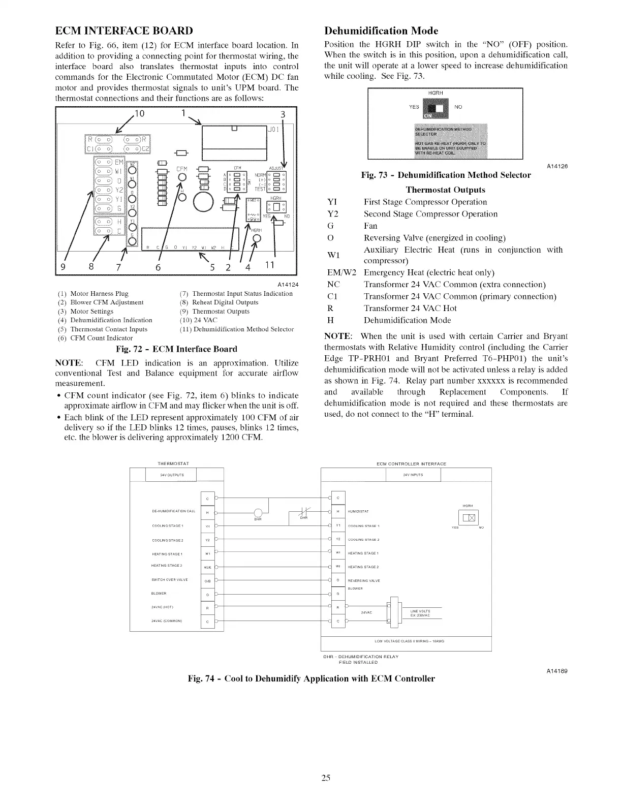
ECM INTERFACE BOARD
Refer to Fig. 66, item (12) for ECM interface board location. In
addition to providing a connecting point for thermostat wiring, the
interface board also translates thermostat inputs into control
commands for the Electronic Commutated Motor (ECM) DC fan
motor and provides thermostat signals to unit's UPM board. The
thermostat connections and their functions are as follows:
10 I _ U jo:3
-[ZZF
F'c;_, W 1Q) 4==_ EFM 0 CF AD,UST
1
9 8 7 6 5
(1) Motor Harness Plug
(2) Blower CFM Adjustment
(3) Motor Settings
(4) Dehumidification Indication
(5) Thermostat Contact Inputs
(6) CFM Count Indicator
A14124
(7) Thermostat Input Status Indication
(8) Reheat Digital Outputs
(9) Thermostat Outputs
(10) 24 VAC
(11) Dehumidification Method Selector
Fig. 72 - ECM Interface Board
NOTE: CFM LED indication is an approximation. Utilize
conventional Test and Balance equipment for accurate airflow
measurement.
• CFM count indicator (see Fig. 72, item 6) blinks to indicate
approximate airflow in CFM and may flicker when the unit is off.
• Each blink of the LED represent approximately 100 CFM of air
delivery so if the LED blinks 12 times, pauses, blinks 12 times,
etc. the blower is delivering approximately 1200 CFM.
Dehumidification Mode
Position the HGRH DIP switch in the "NO" (OFF) position.
When the switch is in this position, upon a dehumidification call,
the unit will operate at a lower speed to increase dehumidification
while cooling. See Fig. 73.
HGRH
YES NO
YI
Y2
G
O
WI
EM/W2
NC
C1
R
H
A14126
Fig. 73 - Dehumidification Method Selector
Thermostat Outputs
First Stage Compressor Operation
Second Stage Compressor Operation
Fan
Reversing Valve (energized in cooling)
Auxiliary Electric Heat (runs in conjunction with
compressor)
Emergency Heat (electric heat only)
Transformer 24 VAC Common (extra connection)
Transformer 24 VAC Common (primary connection)
Transformer 24 VAC Hot
Dehumidification Mode
NOTE: When the unit is used with certain Carrier and Bryant
thermostats with Relative Humidity control (including the Carrier
Edge TP-PRH01 and Bryant Preferred T6-PHP01) the unit's
dehumidification mode will not be activated unless a relay is added
as shown in Fig. 74. Relay part number xxxxxx is recommended
and available through Replacement Components. If
dehumidification mode is not required and these thermostats are
used, do not connect to the "H" terminal.
c
DE HUMIDInCATIONCAL H :_
COOUNGSTA6EI ¥1 73
COOLINGSTAGE2 ¥2:3
HEATINGSTAGE1 Wl :?
HEATINGSTAGE2
W2,E ©
SWITCHOVERVALVE OB :3
BLOWER G D
24VAC_HOT) R D
24VAC_COMMON) C ?)
'\.j
DHR
,_ c
_,, H
( Y2
'- Wl
c w2
c o
c e
( R
{ c
ECM CONTROLLER INTERFACE
j ..........j
HGRH
YES NO
COOLINGSTAGE2
HEATINGSTAGE1
HEATINGSTAGE2
REWRSIN6VALW
BLOWER
24VAC LINEVOLTS
EX 2SOVAC
D
LOWVOLTAGECLASSIIWIRING 10AWG
DHR DEHUMIDIFICATION RELAY
FIELD INSTALLED
Fig. 74 - Cool to Dehumidify Application with ECM Controller
A14189
25
 Loading...