INSTALLATION RECOMMENDATIONS
The Water-to-Air Heat Pumps are designed to operate with
entering fluid temperature between 20°F to 90°F in the heating
mode and between 30°F to 120°F in the cooling mode.
NOTE: 50 ° minimum Entering Water Temperature (EWT) is
recommended for well water applications with sufficient water
flow to prevent freezing. Antifreeze solution is required for all
closed loop applications or EWT less than 45 ° . Cooling
Tower/Boiler and Geothermal applications should have sufficient
antifreeze solution to protect against extreme conditions and
equipment failure. Frozen water coils are not covered under
warranty. Other equivalent methods of temperature control are
acceptable.
Check Equipment and Job Site
Movin_ and Storage
If the equipment is not needed for immediate installation upon its
arrival at the job site, it should be left in its shipping carton and
stored in a clean, dry area. []nits must only be stored or moved in
the normal upright position as indicated by the "UP" arrows on
each carton at all times.
CONFIGURATIONS
Horizontal Configuration
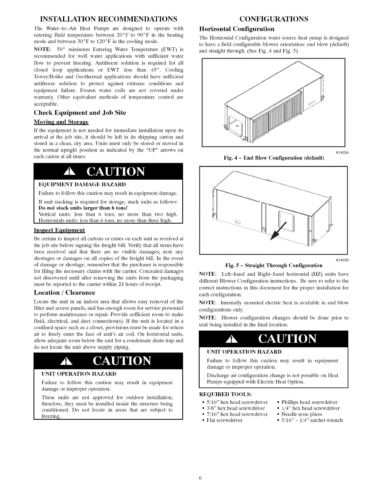
The Horizontal Configuration water source heat pump is designed
to have a field configurable blower orientation: end blow (default)
and straight through. (See Fig. 4 and Fig. 5)
A14034
Fig. 4 - End Blow Configuration (default)
EQUIPMENT DAMAGE HAZARD
Failure to follow this caution may result in equipment damage.
If unit stacking is required for storage, stack units as follows:
Do not stack units larger than 6 tons!
Vertical units: less than 6 tons, no more than two high.
Horizontals units: less than 6 tons, no more than three high.
Inspect Equipment
Be certain to inspect all cartons or crates on each unit as received at
the job site before signing the freight bill. Verify that all items have
been received and that there are no visible damages; note any
shortages or damages on all copies of the freight bill. In the event
of damage or shortage, remember that the purchaser is responsible
for filing the necessary claims with the carrier. Concealed damages
not discovered until after removing the units from the packaging
must be reported to the carrier within 24 hours of receipt.
Location / Clearance
Locate the unit in an indoor area that allows easy removal of the
filter and access panels, and has enough room for service personnel
to perform maintenance or repair. Provide sufficient room to make
fluid, electrical, and duct connection(s). If the unit is located in a
confined space such as a closet, provisions must be made for return
air to freely enter the face of unit's air coil. On horizontal units,
allow adequate room below the unit for a condensate drain trap and
do not locate the unit above supply piping.
[]NIT OPERATION HAZARD
Failure to follow this caution may result in equipment
damage or improper operation.
These units are not approved for outdoor installation;
therefore, they must be installed inside the structure being
conditioned. Do not locate in areas that are subject to
freezing.
A14035
Fig. 5 - Straight Through Configuration
NOTE: Left-hand and Right-hand horizontal (HZ) units have
different Blower Configuration instructions. Be sure ro refer to the
correct instructions in this document for the proper installation for
each configuration.
NOTE: Internally mounted electric heat is available in end blow
configurations only.
NOTE: Blower configuration changes should be done prior to
unit being installed in the final location.
[]NIT OPERATION HAZARD
Failure to follow this caution may result in equipment
damage or improper operation.
Discharge air configuration change is not possible on Heat
Pumps equipped with Electric Heat Option.
REQUIRED TOOLS:
• 5/16" hex head screwdriver
• 3/8" hex head screwdriver
• 7/16" hex head screwdriver
• Flat screwdriver
• Phillips head screwdriver
• 1/4" hex head screwdriver
• Needle nose pliers
• 5/16" - 1/4" ratchet wrench
 Loading...