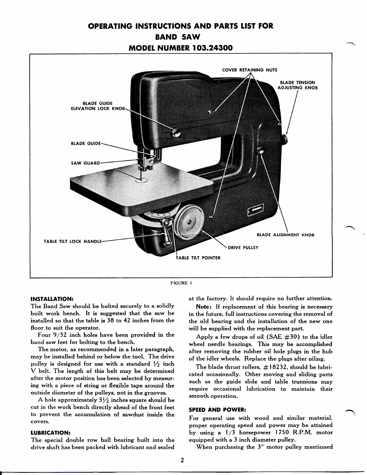
OPERATING
INSTRUCTIONS
AND PAR,TS
LIST FOR.
BAND
SAW
tnoDEt
NUMBER I
03.24300
COVER RETAINING NUTS
BTADE GUIDE
SAW GUARD
TABTE TIIT IOCK
HAN
TABLE TIIT POINTER
FIGURE
I
TNSTATLATION:
The Band Saw
should be bolted
securely
to
a
solidly
built
work bench. It
is suggested
that the
saw be
installed
so
that
the table
is
38
to 42 inches
from the
floor to suit
the operator.
Four
9
/32
inch
holes
have been
provided
in the
band saw feet for bolting to the
bench.
The
motor, as recommended in a later
paragraph,
may be installed behind or below
the tool. The
drive
pulley
is
designed for use with
a
standard
Yz
inch
V belt.
The length of this belt
may
be determined
after the
motor
position
has been
selected
by measur-
ing
with
a
piece
of string
or flexible
tape around
the
outside diameter
of the
pulleys,
not in
the
grooves.
A hole approximately
3t/2
inches sguare should
be
cut in the work
bench
directly ahead
of the
front feet
::#::.nt
the
accumulation
of
sawdust
inside
the
lUBRICATION:
The
special double
row
ball
bearing built into the
drive shaft
has been
packed
with lubricant
and
sealed
at the factory. It
should require no further
attention.
Note: If replacement of
this bearing is necessary
in the future, full instructions covering
the removal of
the old bearing and the
installation
of
the
new
one
will be supplied with the replacement
part.
Apply a
few
drops
of oil
(SAE
#30)
to the
idler
wheel
needle bearings. This may be accomplished
after
removing the rubber
oil
hole
plugs
in
the
hub
of the idler
wheels. Replace
the
plugs
after
oiling.
The
blade
thrust
rollers,
#18232,
should
be
lubri-
cated occasionally. Other
moving and sliding
parts
such as
the
guide
slide
and table
trunnions
rnay
require occasional lubrication
to
maintain their
smooth
operation.
SPEED
AND POWER:
For
general
use
with wood and
similar material,
proper
operating speed
and
power
may
be
attained
by using
a |
/3
horsepower
1750 R.P.M. motor
equipped
with
a
3 inch diameter
pulley.
When
purchasing
the 3" motor
pulley
mentioned