© 2012 SeaStar Solutions Optimus 360 User’s Manual, Rev. C
3-4
These are supplied by the installer and may be mounted in a variety
of locations. Check near the batteries, in the circuit breaker box, or
near the pump control modules or hydraulic pumps. There should be
two 60 amp breakers for each PCM and a 25 amp breaker for each
pair of shift and throttle actuators.
3.5 Circuit Breakers for Optimus 360 System
and Shift and Throttle Control System
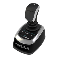
There is a display at the main helm station that shows the system
status and allows system adjustments. A CANtrak display may also
be installed at additional helm stations.
See Section 7.0 for details.
3.4 CANtrak Display
Figure 3-4. CANtrak display.
Part No. ED1700
 Loading...

