Do you have a question about the SeaSTAR i6800 and is the answer not in the manual?
Defines critical safety terms like Danger, Warning, Caution, and Notice.
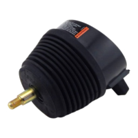
Guidance on actuator placement, labeling, and secure mounting methods.
Details on the CAN2 network structure, including tees and terminators.
Guides through the basic system configuration using the CANtrak display.
Detailed steps for configuring actuators and their parameters.
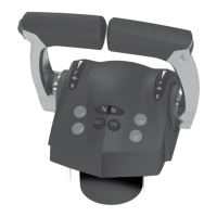
Configures actuator types (shift/throttle) and instances (port/starboard) via CANtrak.
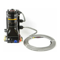
Details on mechanically installing and adjusting the shift and throttle cables.
Specific instructions for connecting and adjusting the shift cables to the engine and actuator.
Specific instructions for connecting and adjusting the throttle cables to the engine and actuator.
Procedure for fine-tuning shift actuator parameters for proper gear engagement.
Configuration of control head parameters like sync modes, max RPM, and shift delay.
Detailed steps for configuring actuators and their parameters using Datalink.
Configures actuator types and instances using the Datalink software.
Describes mechanical cable installation and adjustment procedures using Datalink.
Final adjustments for shift actuators using Datalink for precise gear engagement.
Final adjustments for throttle actuators using Datalink for synchronized RPM.
Configuration of control head parameters using the Datalink software.
| Brand | SeaSTAR |
|---|---|
| Model | i6800 |
| Category | Boating Equipment |
| Language | English |