4-8
© 2013 SeaStar Solutions i6800 Installation Supplement, Rev. C
4.2.2.1 – Shift Cable Installation
Engine Side
1. Position the engine’s shift linkage in the neutral position.
2. Connect the cables to the engine using the appropriate adapters.
For new adapter kits, refer to the instructions provided with the
kit. If reusing the existing cable ends, position the cable ends
approximately half way down the threaded portion
of the cable.
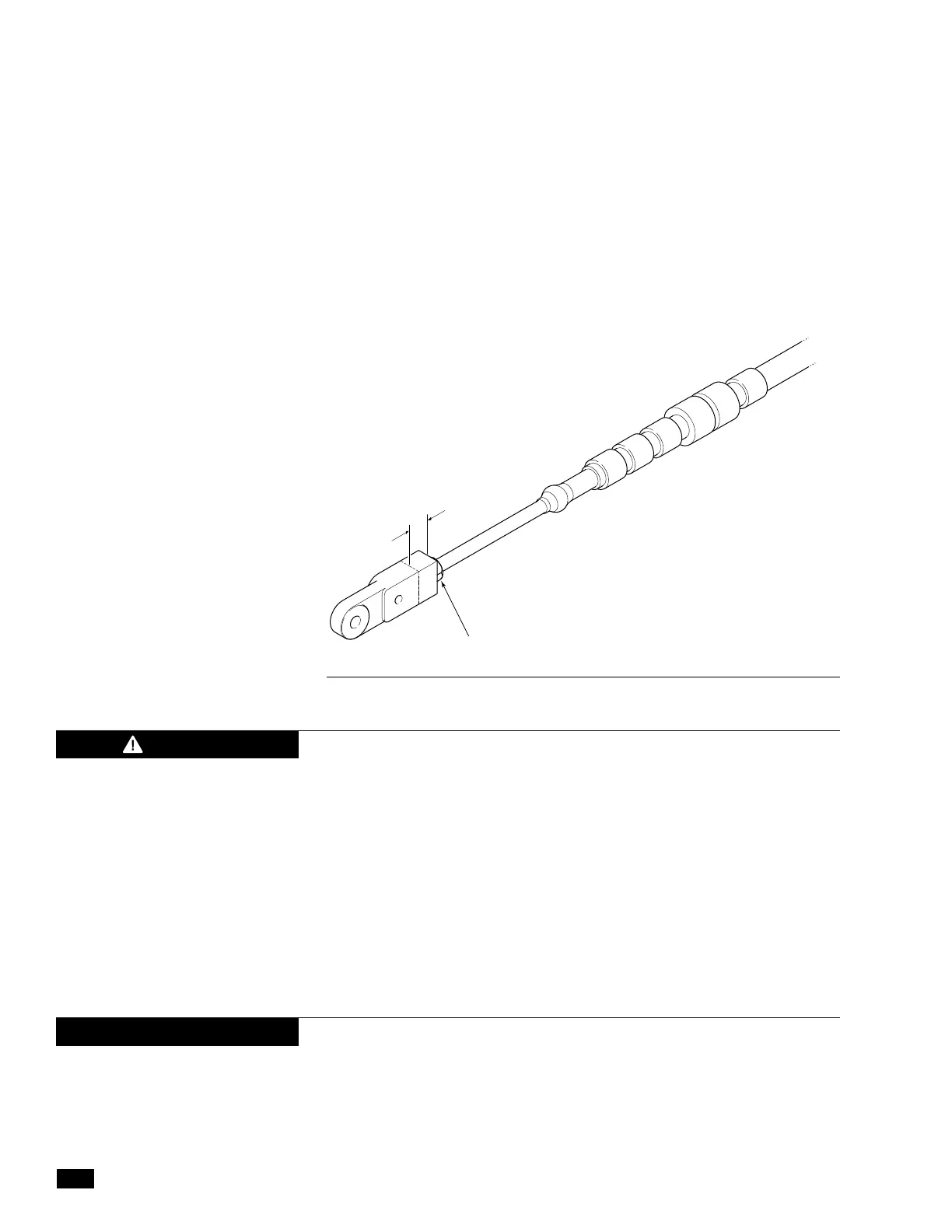
Always use jam nuts to lock the
cable end in place. See figure 4-12.
There must always be at least 3/8” of thread engagement on the
engine side cable end. See figure 4-12. If correct adjustment cannot
be achieved while maintaining 3/8” of thread engagement, longer
cable ends may be required.
Actuator Side
1. Position the U-shaped steel retainer clip (A) into the slot on the
actuator rack as shown in figure 4-13.
2. Screw the adjustment barrel (B) onto the cable end to the point
where the cable can be set into the actuator with the barrel
engaging the steel retainer clip (A) and the cable housing groove
(C) engaging the cable mount in the actuator. Ensure there is
enough cable sticking out of the adjustment barrel (B) to install
and tighten the lock nut (D).
If there is not enough cable protruding to install the lock nut, adjust the
cable end on the engine side to lengthen the cable at the actuator side.
3. Lay the cable into the actuator and install the dust seal (E).
4. Re-install the actuator cover (See figure 4-11).
5. Repeat for the other shift actuator, if applicable.
NOTICE
CAUTION
Figure 4-12. Cable End, engine side installation.
JAM NUT
MINIMUM CABLE
ENGAGEMENT
3/8" (9 mm)


 To Next Page