Operation
radio, CD player, AUX IN connection or navi-
gation sy
stem.
●
The arrangement of switches and controls
on right-hand drive models* may be slightly
different from the layout shown in
››
› page 100. However, the symbols used to
identify the controls are the same.
Instruments and warning/control lamps
Ins
truments
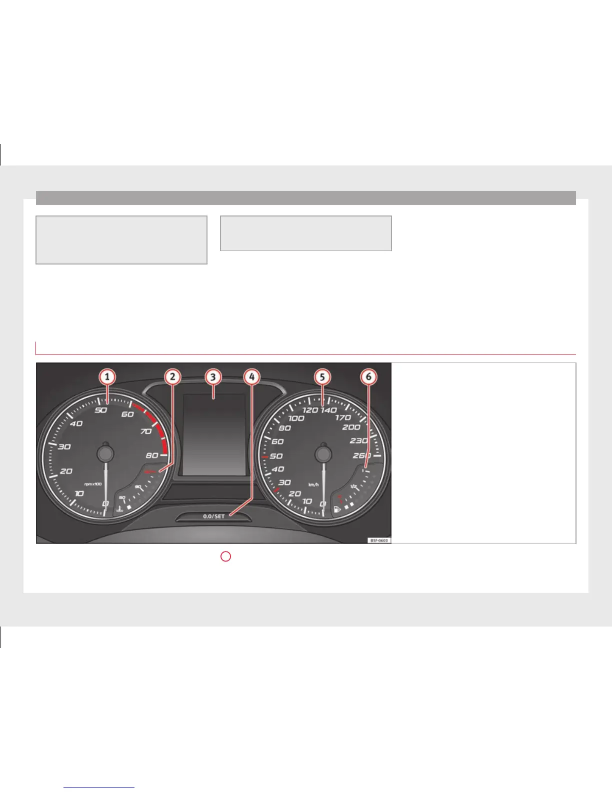
View of instrument panel
Fig. 115 Instrument panel, on dash panel
Details of the instruments ›
›
› Fig. 115: Rev counter (with the engine running, in
hundreds of revolutions per minute).
1
The beginning of the red zone of the rev
c
ou
nter indicates the maximum speed in
any gear after running-in and with the
102