Replacement instructions
seca 284/ 285
13.09.2010 /KSP 9 30-34-00-811
3 Display
Please be sure to observe the sequence listed below when removing/fitting the parts!
3.1 Replacing the front glass, electronics and radio module
•
••
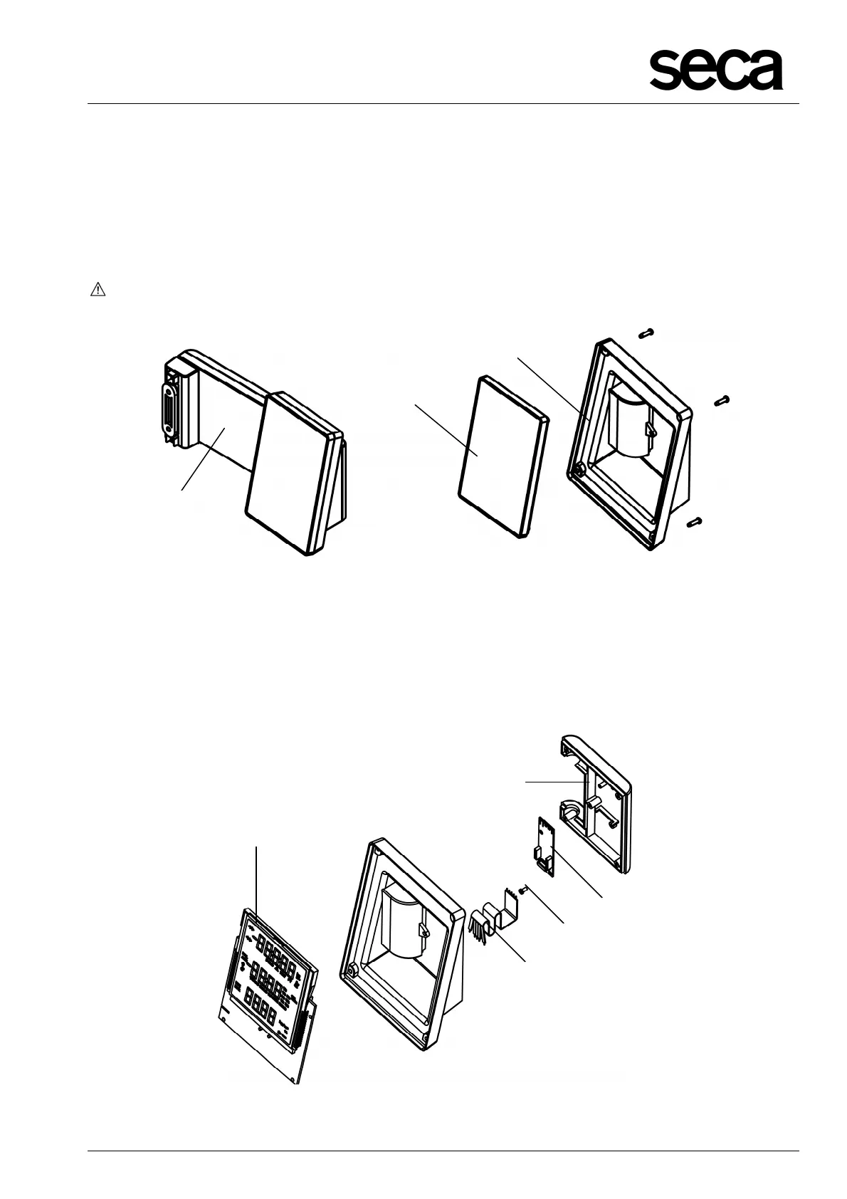
• Remove the display unit completely (E).
•
••
• Carefully detach the front glass (K) from the display unit (F).
The modular cable (A, Fig.12) and the 5-pole flat cable (G, Fig. 11) are connected to
the extended NEC2 display unit (H, Fig. 11)!
Figure 10: Replacing front glass and display housing
• Remove the modular cable (A, Fig. 12) from the plug-in connection for the extended
NEC2 display unit (H). Take extreme care to ensure no stress is applied to the 5-
pole flat cable (G) which is soldered to the extended NEC2 display unit (H)!
• Now you can remove the screw (U) which secures the radio module (V) to the rear
panel of the housing cover (W).
Figure 11: Replacing extended NEC2 display unit and 5-pole flat cable
E
K
F
 Loading...