Service Manual Replacement instructions
12.09.02/Rei 1 30-34-00-678a
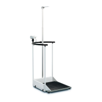
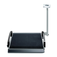
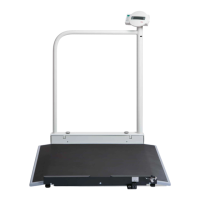
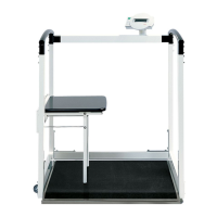
seca 644, 645
The references to pages and items relate to the replacement instructions drawing, Pages 5 – 14.
The power supply unit must not be connected.
We urgently recommend that you remove the rechargeable battery pack before starting any work on the unit:
Remove the 2 screws (Page 11, Item 11.1) and the battery cover (Item 11.2).
Pull the rechargeable battery connection apart (cable).
Remove the rechargeable battery pack (Item 11.3).
ESD protection measures must be taken whenever work is performed on electronic components.
Removal
1. Removing and dismantling the rail (Page 5).
Disengage the cable (Item 5.1) under the scale.
Release the cable from the cable terminals.
Remove the two screws (Item 5.2).
Remove the three screws (Item 5.3).
Lift off the complete display unit from the holder (Item 5.4).
The display is still connected with the column (Item 5.6) via the cable (Item 5.5).
To prevent premature cable wear, the housing should be fastened to the column.
Remove the screw (Item 5.7) and lift off the display bearing (Item 5.4).
Lift off the rail (Item 5.8).
If required: Replace the plugs (Item 5.9).
2. Removing the torsion box and the column (Page 6).
Remove the self-tapping screw (Item 6.1).
Remove the triangular cover (Item 6.2) with the three self-tapping screws (Item 6.3).
Remove the torsion box cover (Item 6.4) with the 5 self-tapping screws (Item 6.5).
Hold the torsion box and column assembly (Item 6.6) and remove the three screws (Item 6.7).
Remove the torsion box and column assembly.
If required: Remove the 3 screws (Item 6.8) and pull out the rail bearing (Item 6.9).
If required: Remove the plug (Item 6.10).
3. Removing the wheel box and the columns (Page 7).
Remove the triangular cover (Item 7.1) with the three self-tapping screws (Item 7.2).
Remove the wheel box cover (Item 7.3) with the 5 self-tapping screws (Item 7.4).
Hold the wheel box and column assembly (Item 7.5) and remove the three screws (Item 7.6).
Remove the wheel box and column assembly.
If required: Remove the 3 screws (Item 7.8, Item 7.9) and
pull out the rail bearings (Item 7.10, Item 7.11).
If required: Remove the plugs (Item 7.12, Item 7.13).
Attention: The plug (Item 7.13) has a hole for the cable gland.
Once you have removed the rail bearing (Item 7.8), you can take out the display (Item 7.14).
It is easier to enter the cable when the plug (Item 7.13) is out.