Maximum battery charging current:
0,35A
Module disconnect battery when its
voltage is less than:
9,5V
Black
Red
12V battery
7Ah/20HR
3.15A
COM
+BELL
20VAC COM -PGM+BELL
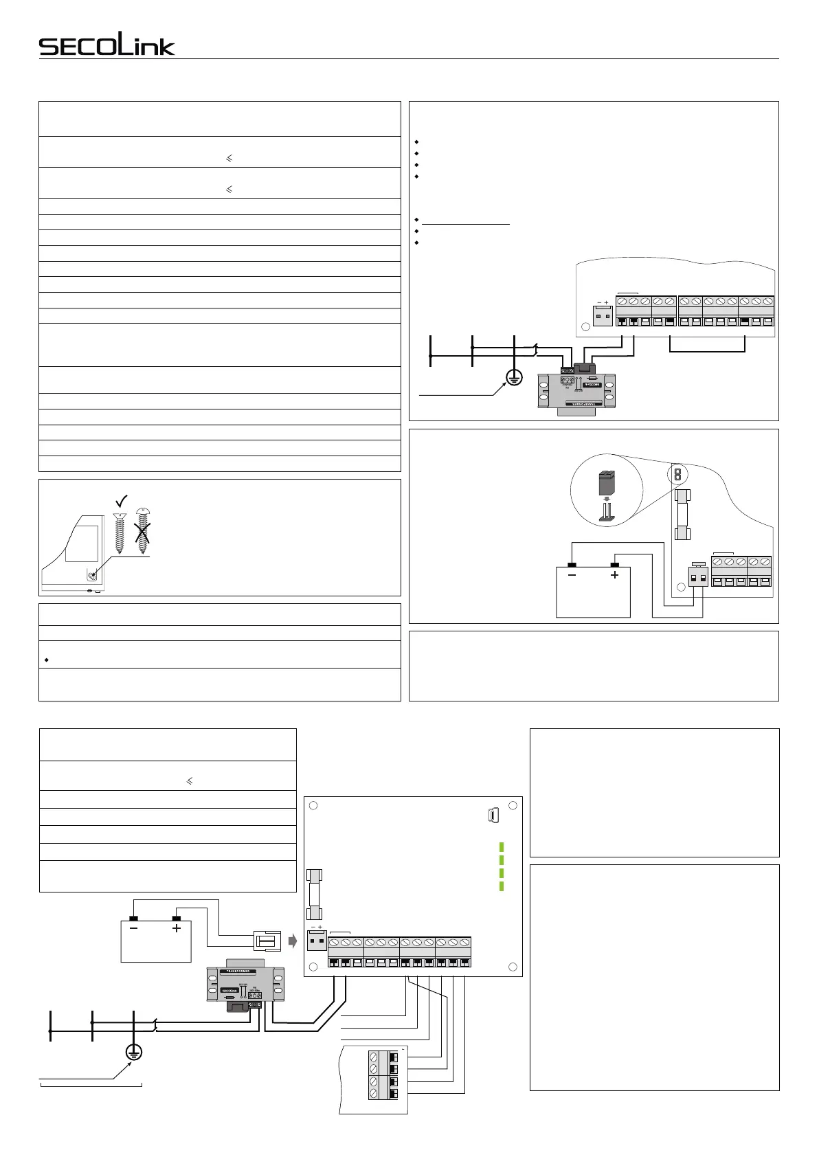
System start-up with no 230V AC power
Non-volatile memory
Connect 12V battery to P
series control panel by using a
BAT connector. Use the
jumper to close the shown pins
for 1 second. The system will
start operating; however, AC
loss trouble will be indicated.
Jumper
Maximum current out of +AUX:
Maximum battery charging current:
Low battery voltage threshold:
1,5 A
2 A
+1 A
+0,35 A
10,5 V
Maximum load ratings and electrical characteristics
of P series control panels
Maximum current out of +BELL:
Maximum current out of +PGM for P16:
Maximum current out of +PGM for P32, P64:
+2,0 A
+0,5 A
+0,9 A
Control panel disconnect battery when it’s voltage is less than: 9,5 V
Minimum AC voltage on 20 VAC:
Note: with ~16 V on 20 VAC max DC current generated by
control panel power supply is 0,7A.
Maximum current of a fast blowing fuse used in battery circuit:
~16 V
3,15 A
Maximum AC voltage on :
Note: higher than V voltage can damage control panel
20 VAC
~22 .
Maximum voltage on +AUX, +BELL, +PGM outputs:
Minimum voltage on +AUX, +BELL, +PGM outputs:
~22 V
+13,9 V
+12,0 V
Max current of a slow blowing fuse used in primary AC circuit:
Maximum AC power consumption:
250 mA
240 mA
Maximum long term output current of P16 control panel:
(I + I + I + I 1,5 A )
+AUX
+BELL
+PGM
BAT. CHARGE
Maximum long term output current of P32, P64 control panel:
(I + I + I + I 2 A )
+AUX
+BELL
+PGM
BAT. CHARGE
Service mode is now enabled and service PIN is restored to 0000. To reset user
PIN follow the steps:
do not block service by pressing ENT;
press arrow key to navigate in the menu;
go to: Main Menu/Settings/Users/Edit Users/ enter 0000 /Reset PIN to
default/YES
Restoring service PIN to default value
Electrical characteristics and additional information
Wire
Maximum current into -PGM:
-0,3A
To restore default value (0000) for service PIN, follow these steps:
disconnect control panel from 20 V AC power supply;
disconnect control panel from back-up battery;
use a wire to short-circuit the -PGM and zone Z1;
connect control panel to 20 V AC power supply.
Control panel has non-volatile memory to store all parameters, event log, and the
last control panel status. System status returns to the same status as it was before
the power supply was disconnected.
Keypad mounting
Keypad
Use only self-tapping screws with a flat (countersunk)
head (3x30 PH) to mount keypad’s plastic on the wall .
Make sure the screw is fastened completely and its
head is hidden in the plastic. Other shapes of screws
that are not completely screwed in, may touch keypad
electronics and cause damage of keypad.
COM
+BELL
DAT
+AUX
Z1
COM
Z2
CLK
COM
-PGM
+PGM
20 VAC
20 VAC
Maximum long term current out of PWR20:
Maximum current out of +AUX:
2,0A
+1A
Maximum load ratings and electrical
characteristics of PWR20
Maximum current out of +BELL:
Maximum current into -PGM1:
+2A
-0,05A
Wiring of modules in large or high security level system
12V battery
7Ah/20HR
Black
Red
Outdoor siren's safe wiring
Use a transformer, other than a control panel, and a
rechargeable 12V 7Ah battery to power up PWR20. If
an alarm system includes PWR20, it is recommended
to wire an outdoor siren to the PWR20 terminals
+BELL, -PGM1, (-PGM2), and COM same as shown
on page 2. Failure of siren’s internal battery or the siren
itself will not affect the performance of an alarm
system.
PWR20 – power supply module
with a bus repeater
Repetition of the system bus (KRbus) is a perfect
solution when some system modules (PROX8,
EXTx16) are placed outside the premises or in an area
that is not protected by detectors. It is recommended to
wire all outside proximity readers or keypads located
near the entry door to the repeated (by PWR20) bus.
An attempt to make a short circuit on the outside
module will make no affect to system’s performance.
PWR20 will detect the short circuit on repeated bus
and will disconnect it from the main bus. Terminals
CLK-I and DAT-I are inputs for the main bus, terminals
CLK-O and DAT-O are outputs of the repeated bus. To
supply power to modules, PWR20 output +AUX must
be used.
Module address LED
Low battery indicator
Battery charging on
Overload of +BELL or + AUX.
X1
BAT
OVL
CHG
LOW
MOD
PWR20
3.15A
DAT-O
CLK-O
COM
+12V
+12VCLK COMDAT
COM
DAT
+12V
CLK
DAT from Pxx
CLK from Pxx
COM from Pxx
+BELL
COM
-PGM1
TMP
COM
+AUX
CLK-I
CLK-O
DAT-I
DAT-O
20 VAC
DAT-O
CLK-O
COM
+12V
+12VCLK COMDAT
COM
DAT
+12V
CLK
Module
Live
wire
L
Neutral
wire
N
Protective
Earth wire
PE
Power supply
distribution board
Main Protective
Earthing terminal
Fuse
250mA
AC power transformer:
Primary winding: 230V AC 50Hz
Secondary winding: 20V AC 50Hz
~
~
(I + I + I 2 A )
+AUX
+BELL
BAT. CHARGE
Page 3
+BELL
~20 VAC
COM
-PGM1
TMP
COM +AUXCLK-I CLK-O
DAT-I DAT-O
Live
wire
L
Neutral
wire
N
Protective
Earth wire
PE
Main Protective
Earthing terminal
Fuse
250mA
20VAC COM -PGM +PGM COM CLK DAT +AUX Z1 COM Z2+BELL
-10°C to +55°C
12 years
Operating temperature
Operating temperature range:
Note: ambient temperature over 40 may reduce life expectancy.°C
Note: poor ventilation of the cabinet increases ambient temperature.
Calculated life expectancy at 40 ambient temperature:
for
°C
P16, P32, P64 control panels:
Intruder alarm system
Wiring manual
Control Panels P16, P32, P64