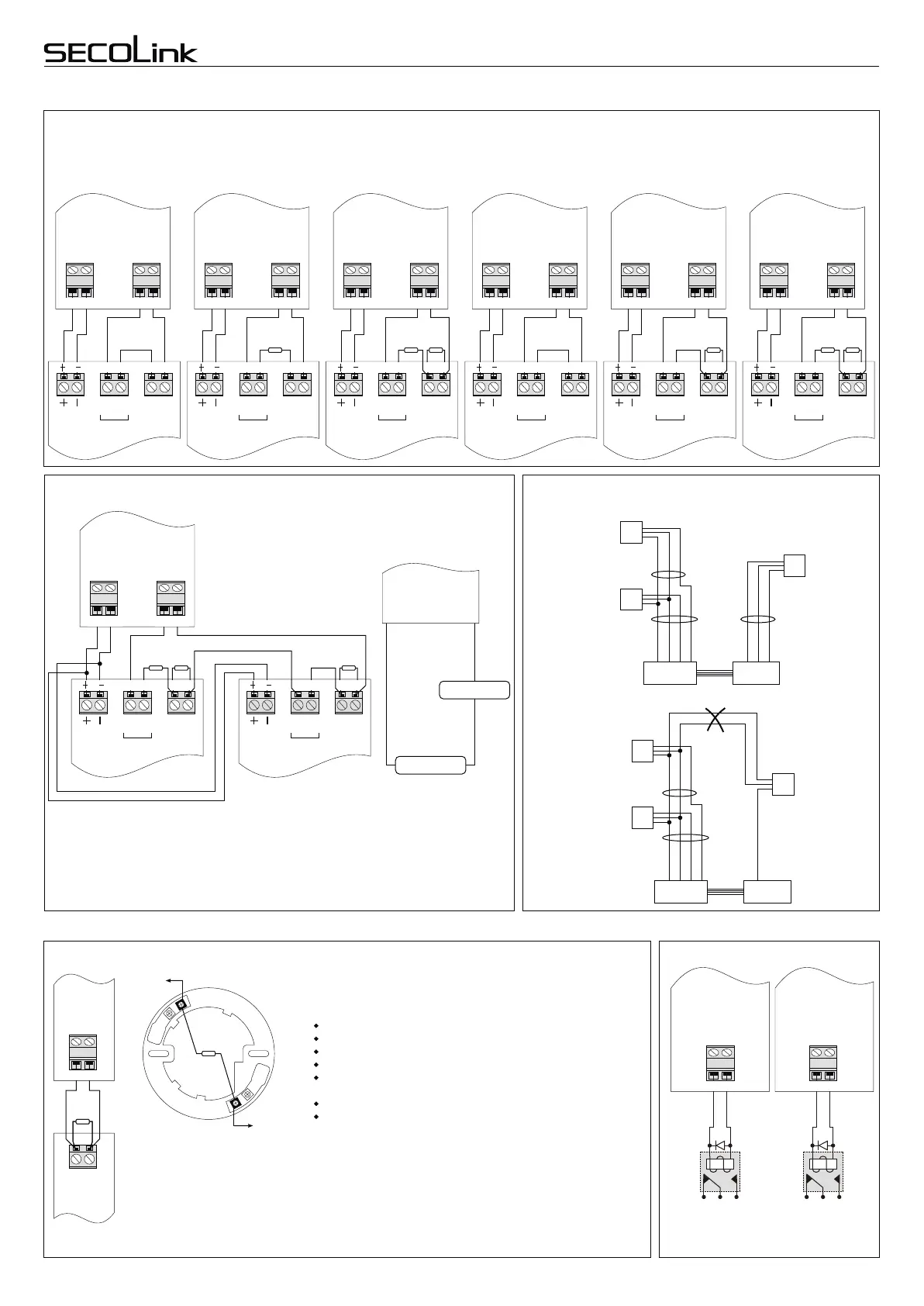
Wiring of zones
Normally closed contact
(NC)
Normally closed contact
with one resistor
(NC/EOL)
Normally closed contact
with two resistors
(NC/DEOL)
Normally open contact
(NO)
Normally open contact
with one resistor
(NO/EOL)
Normally open contact
with two resistors
(NO/DEOL)
Wiring of single zones
Wiring of double zones
Detector
Control panel or
module
Control panel or
module
Control panel or
module
Control panel or
module
Control panel or
module
Control panel or
module
+AUX
COM
Z1
COM
Tamper
Z2
Control
panel
+AUX
COM
Z2
Detector
Detector
Z1
Cable
Cable
+AUX
COM
Detector
+AUX
COM
Z1
Cable
EXM800
+AUX
COM
Z1
Z2
+AUX
COM
Z2
Detector
Detector
Z1
Cable
Cable
+AUX
COM
Detector
EXM800
ATTENTION! Avoid power supply loops
1kΩ 620Ω
Control panel
+AUX
COM
Z1
COM
Detector A
T1
T2
NC*
C
Tamper
Detector B
T1
T2
NC*
C
Tamper
300Ω
Detector A
Detector B
* - Detector contact must be NC or NO.
Control panel
Correct wiring
Wrong wiring
1kΩ
+AUX
COM
Z1
COM
Tamper
Detector
1kΩ
+AUX
COM
Z1
COM
Tamper
Detector
+AUX
COM
Z1
COM
Tamper
Detector
+AUX
COM
Z1
COM
Tamper
Detector
+AUX
COM
Z1
COM
Tamper
Detector
Wiring samples
Wiring of a 2-wire smoke detector
Detector
Control
panel
-Z5F
+Z5F
NO
Note: smoke detectors, produced
by different manufacturers, may
have a different terminals layout.
For more information
’
check
detector wiring manual provided by
the manufacturer.
Terminals of smoke detector
To -Z5F
To +Z5F
It is recommended to use diode to
supress voltage surges on relay.
Wiring of relays
Smoke detectors can be triggered by dust. Therefore, to prevent
false alarms, it is recommended to verify the fire alarm. For
verification, the user must activate system settings listed below.
Zone settings:
Zone address: 00_5 (control panel zone terminals -Z5F, +Z5F);
Zone loop type: NO/EOL;
Zone definition: 24h smoke;
Attribute assigned to a zone: Fire verification;
Reset time must be set;
System times settings:
Detector settling time must be set;
Fire verification time must be set;
Operation: In order to check a triggered fire detector, detector's
power supply has to be turned off and turned on again. The system
turns the -Z5F off for a Reset time. When the reset time expires, the
system turns the -Z5F on again and waits for the detector to settle
(Detector settling time). After that, the system checks the detector
again for a time period set in the menu under the Fire verification
time setting. If the detector is triggered again, then this means that
the alarm really occured.
Control panel or
module
+AUX
-PGM
Control panel or
module
+PGM
COM
T1
T2
NC
C
NO
NO
NO
Control
panel
2,2kΩ
T1
T2
NC
C
T1
T2
NC
C
T1
T2
C
T1
T2
C
T1
T2
C
+AUX COM Z1 COM+AUX COM Z1 COM
12V CT2 NCT1 12V CT2 NCT1
1kΩ 1kΩ 1kΩ 1kΩ
12V CNCT2T1 12V CT2 NOT1 12V CNOT2T1 12V CNOT2T1
+AUX COM Z1 COM +AUX COM Z1 COM +AUX COM Z1 COM+AUX COM Z1 COM
+AUX COM Z1 COM
CNC* 12V T2T1 CNC*T2T1 12V
D1
NCNC
NONO
Relay
D1
NCNC
NONO
Relay
+AUX -PGM+PGM COM
2,2kΩ2,2kΩ
-Z5F +Z5F
Page 5
Intruder alarm system
Wiring manual
Control Panels P16, P32, P64