Typical system installation example - SECOLINK P16, P32
Installation of GSVU module and PSTP communicator
P16, P32, P64
GSVU
PSTP
3.15A
P16, P32, P64
20VAC COM -PGM +PGM COM CLK DAT +AUX Z1 COM Z2 +AUX Z3 COM Z4 -Z5F +Z5F Z6 +AUX Z7 COM Z8+BELL
ANT
3.15A
+AUX
COM
Z2
Z6 +AUX Z7 COM Z8
ANT
PSTP
TIP
RING
T-1 R-1
20VAC COM -PGM +PGM COM CLK DAT +AUX Z1 COM Z2 +AUX Z3 COM Z4 -Z5F +Z5F+BELL
OPENOPEN
LOCKLOCK
GSVU
P16, P32, P64
If the system must be expanded with other modules, that do not have a direct
connection with the control panel (for example LAN800) then it could be installed
next to the panel board. Crosses and a dashed line present commonly used
locations of modules. Module's mounting holes should correspond to cabinet's
rear wall holes.
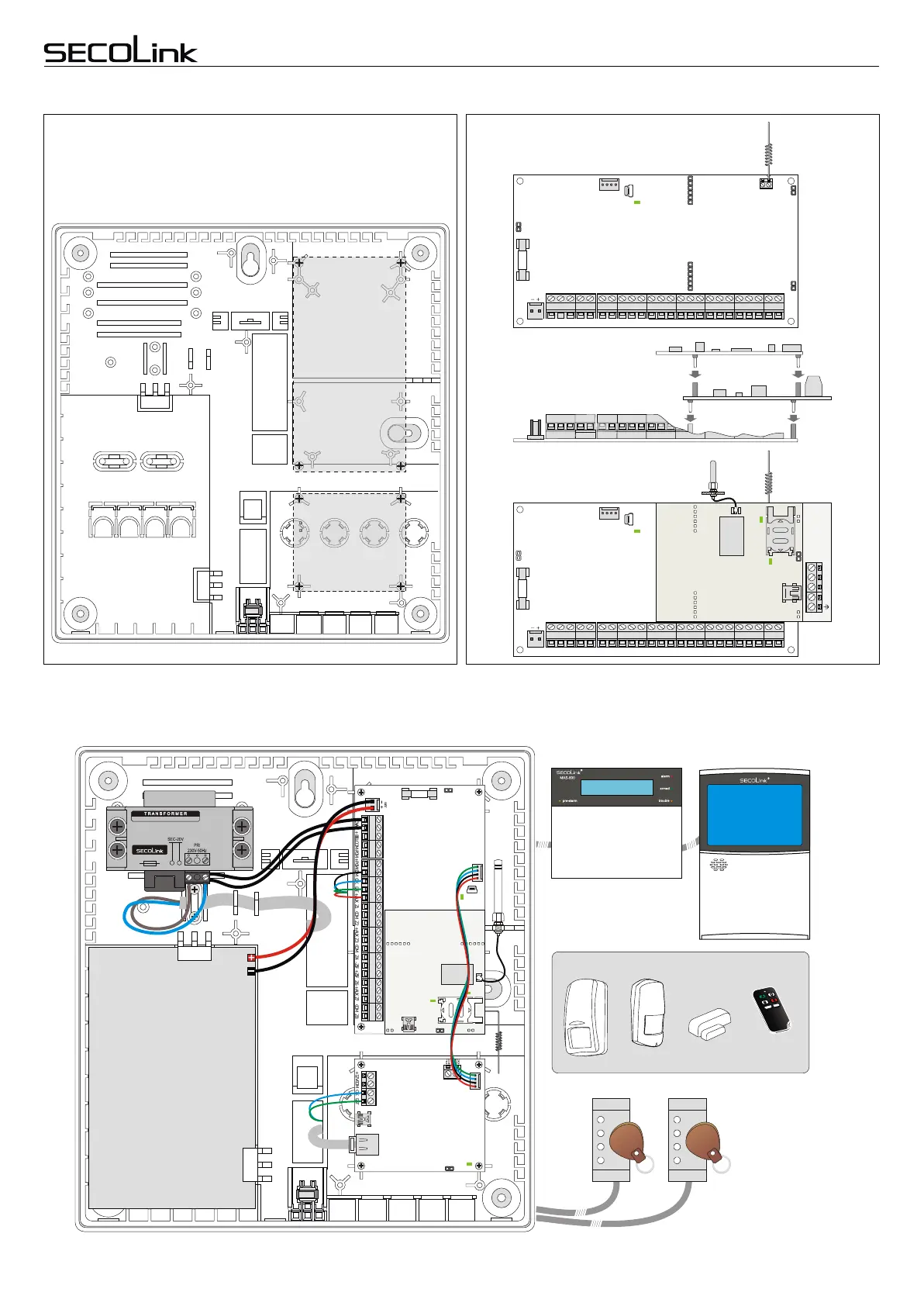
Installation of the control panel and GSM/GPRS or LAN module
Installation of modules in CAS6 plastic cabinet
+12V
COM
CLK
DAT
RING TIP
BAT
CLK DAT +AUX Z1 COM Z2 +AUX Z3 COM Z4 -Z5F +Z5F Z6 +AUX Z7 COM Z820VAC COM -PGM +PGM+BELL COM
KM20B
LAN800
P16
KM24
PROX8 PROX8
12V battery
7Ah/20HR
OPENOPEN
LOCKLOCK
GSVU
Typical system installation example - SECOLINK P16, P32
Installation of GSVU module and PSTP communicator
P16, P32, P64
GSVU
PSTP
3.15A
P16, P32, P64
20VAC COM -PGM +PGM COM CLK DAT +AUX Z1 COM Z2 +AUX Z3 COM Z4 -Z5F +Z5F Z6 +AUX Z7 COM Z8+BELL
ANT
3.15A
+AUX
COM
Z2
Z6 +AUX Z7 COM Z8
ANT
PSTP
TIP
RING
T-1 R-1
20VAC COM -PGM +PGM COM CLK DAT +AUX Z1 COM Z2 +AUX Z3 COM Z4 -Z5F +Z5F+BELL
OPENOPEN
LOCKLOCK
GSVU
P16, P32, P64
If the system must be expanded with other modules, that do not have a direct
connection with the control panel (for example LAN800) then it could be installed
next to the panel board. Crosses and a dashed line present commonly used
locations of modules. Module's mounting holes should correspond to cabinet's
rear wall holes.
Installation of the control panel and GSM/GPRS or LAN module
Installation of modules in CAS6 plastic cabinet
+12V
COM
CLK
DAT
RING TIP
BAT
CLK DAT +AUX Z1 COM Z2 +AUX Z3 COM Z4 -Z5F +Z5F Z6 +AUX Z7 COM Z820VAC COM -PGM +PGM+BELL COM
KM20B
LAN800
P16
KM24
PROX8 PROX8
12V battery
7Ah/20HR
OPENOPEN
LOCKLOCK
GSVU
P16, P32, P64
LAN800
Page 6
Intruder alarm system
Wiring manual
Control Panels P16, P32, P64
BK1, BK2,
BK3, BK4,
BV3, BT1
LT5
BP1 BP2