5.10.5.5 PTZ
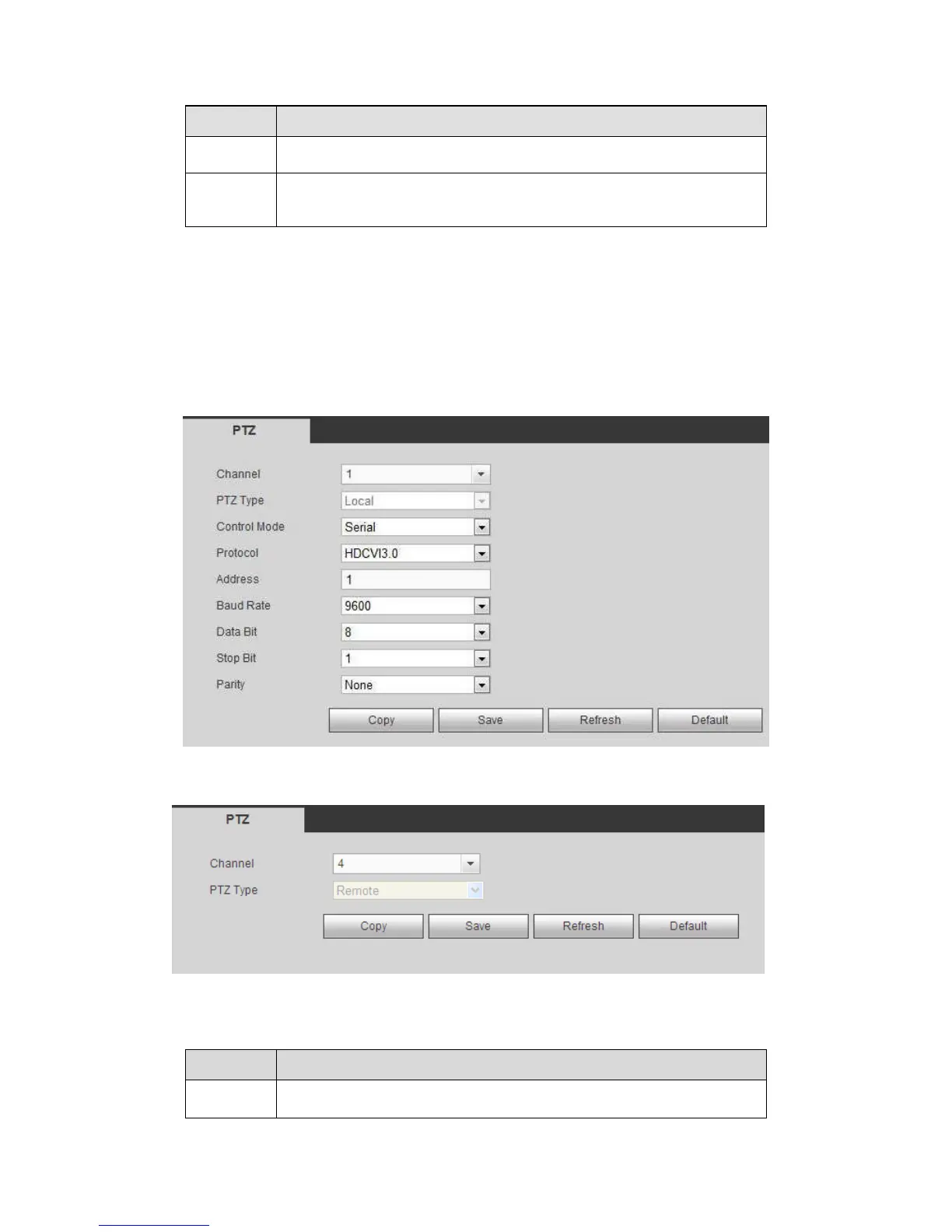
The PTZ interface is shown as in Figure 5-124 and Figure 5-125.
Before setup, please check the following connections are right:
PTZ and decoder connection is right. Decoder address setup is right.
Decoder A (B) line connects with DVR A (B) line.
Click Save button after you complete setup, you can go back to the monitor interface to
control speed dome.
Figure 5-124
Figure 5-125
Please refer to the following sheet for detailed information.