HF Series Generators -- RAD Console
Operation
OM-0279R0
42
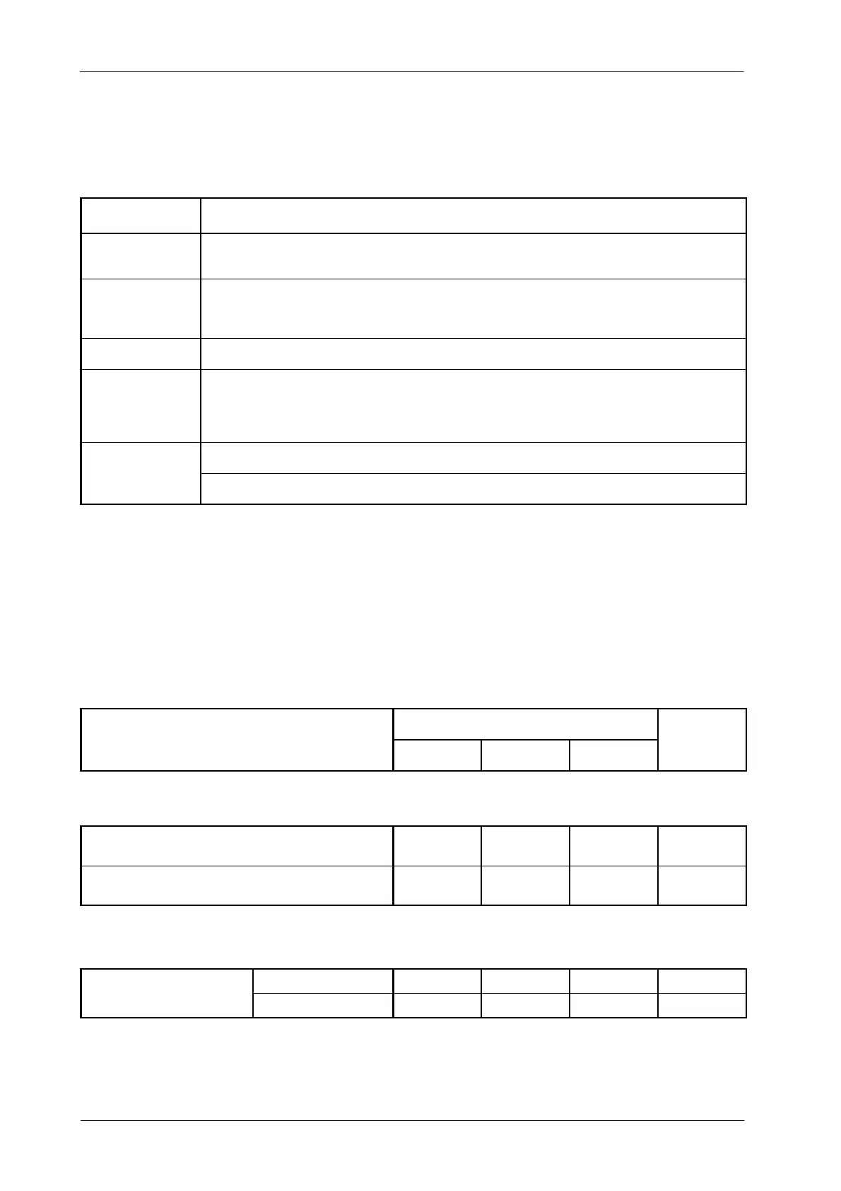
6.2 RANGE OF RADIOGRAPHIC PARAMETERS
PARAMETER RANGE
kV
From 40 kV to 125 kV or 150 kV in 1 kV steps.
(Depending on the Generator model)
mA
From 10 mA to 800 mA through the following mA stations:
10, 12.5, 16, 20, 25, 32, 40, 50, 64, 80, 100, 125, 160, 200, 250, 320, 400, 500, 640, 800.
(Depending on the Generator model)
mAs Product of mA x T ime values from 0.1 mAs to 500 mAs (640 mAs on request)
Exposure Time
From 1 millisecond to 10 seconds through the following Time stations:
Milliseconds: 1, 2, 3, 4, 5, 6, 8, 10, 12, 16, 20, 25, 32, 40, 50, 64, 80,
100, 125, 160, 200, 250, 320, 400, 500, 640, 800.
Seconds: 1, 1.25, 1.6, 2, 2.5, 3.2, 4, 5, 6.4, 8, 10.
mAs: 0.1 mAs to 500 mAs
AEC
Exposure Time: Nominal shortest irradiation Time = 1ms
6.3 DUTY CYCLE
The Generator duty cycle is continuous, but limits should be set during
installation depending on the capacity of the X-ray Tube.
6.4 PHYSICAL CHARACTERISTICS
DIMENSIONS
COMPONENT
Length Width Height
WEIGHT
LINE POWERED GENERATORS
Compact Generator Cabinet
(for only 1 Tube (LSS))
445 mm 360 mm 568 mm 72 kg
Compact Generator Cabinet
(for 1 or 2 Tubes (LSS or HSS))
592 mm 360 mm 690 mm 95 kg
CONTROL CONSOLE
with Handswitch support 545 mm 290 mm 50 mm 6kg
R
D Console Graphic Display
w/o Handswitch support 430 mm 290 mm 50 mm 6kg