TA Operation/Maintenance Instructions Page 25 of 36
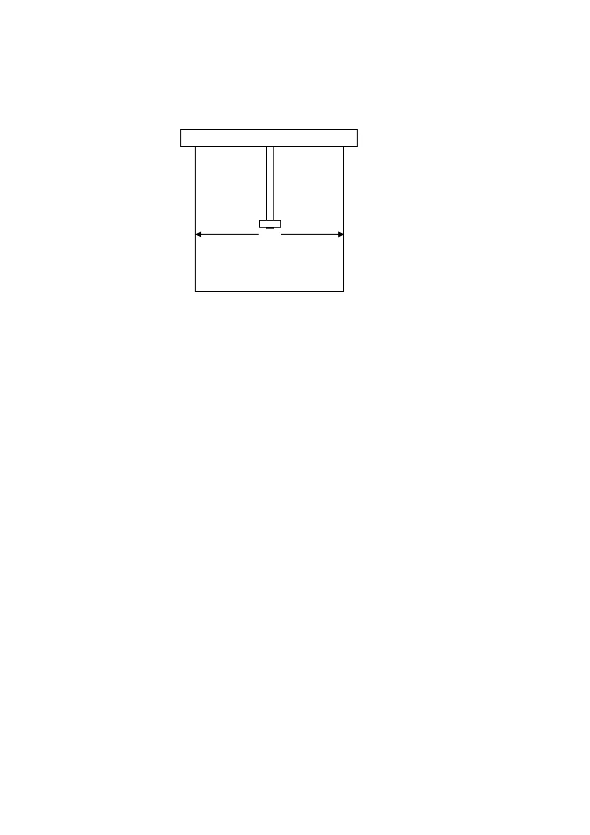
Roll the table through its full travel, checking that the gap remains the same all the way
along the table. If the gap varies from one end to the other loosen the jib support bracket
and adjust it either leftwards or rightwards. It is important that the bracket is re-tightened
once adjustments have been made (24mm spanner required).
Move to the left if the fence falls Move to the right if the fence
away from the table during its comes into contact with the
travel. table during its travel.
After the table has been lined up square the crosscut fence to the blade and re-set the
90
0
stop if necessary.
Looseness or slop between the table rollers and bar can also affect crosscut accuracy.
Ensure that there is no sideways play in the two hardened rollers, and tension the bottom
bearing on its adjustable strap to suit. Do not over-tighten, as this will impair the movement
of the table and cause excess wear on the slide rail.
9.3 Optional 1220mm Panel Sizing Table Setting & Installation
On removing the protective packaging, the Panel Sizing Table should be lifted off its
supporting blocks and placed on the floor.
Next remove the tape securing the two table support jibs to the rolling table shaft and
check that both jibs run freely. Clean the protective oil from the rolling table shaft and
remove the two slide bearings from the pins located at the end of either jib (note:the slide
bearings will late have to be replaced onto the correct jib, do not get them mixed up).
Using a 6mm allen key remove the table stop screw located on the underside of the
operating end of the rolling table shaft. Lift the Panel Sizing Table and roll it completly onto
the shaft. With one person holding the weight of the table, the other person should slide
the jib bearings onto the two shafts located on the underside of the rolling table. Swing
the jibs into position and lower the two slide bearings onto the jib pins. Refit the table stop
screw. Lightly oil all moving parts. Finally, undo the two two shaft locking knobs and slide
the slide the shaft forwards from the operating end util it stops. This is now in the full
1220mm capacity position. Re-tighten the locking knobs and check that the table runs
smoothly along its full travel.
Fault finding checklist
The Panel Sizing Table has been factory fit and tested, however if any problems are
encountered with smooth and accurate operation of the unit the following checks should
be undertaken:
 Loading...