Example - 10 : Sensing Distance (Ultrasonic Ranger Sensor)
WHAT ARE WE DOING HERE?
This example shows how to measure the distance to obstacles using the ultrasonic sensor and
display the value on a 4-Digit Display (centimeters).
THE CIRCUIT
● Grove-Ultrasonic Ranger Sensor x1
● Grove-4-Digit Display x1
● Grove cable x2
● Grove-Base BoosterPack x1
● LaunchPad Development Kit
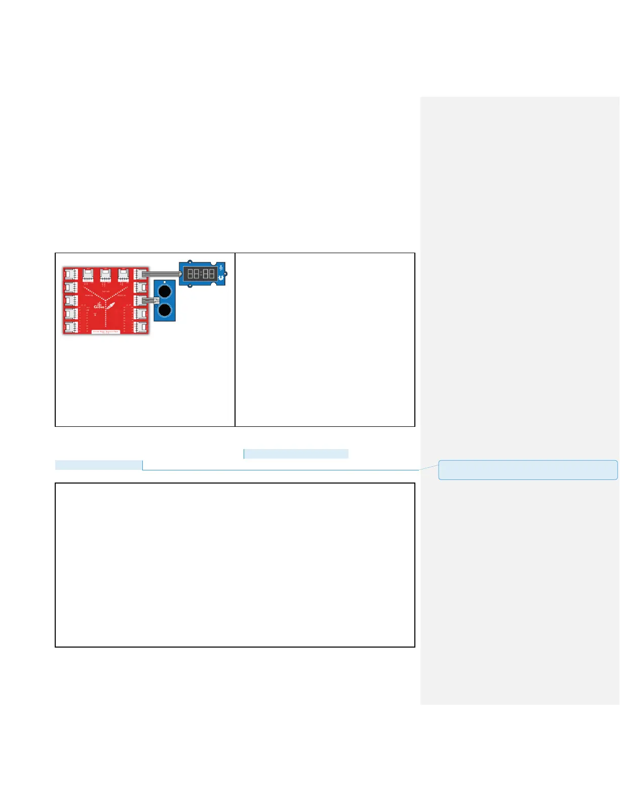
Connections:
Plug the Grove-Ultrasonic Sensor module into
Digital Grove connector J15 on the
BoosterPack. This will link the SIG pin of the
ultrasonic sensor to pin 38 of the LaunchPad.
Plug the Grove-4-Digit Display into Digital
Grove connector J13. This will link the 2 SIG
pins (CLK & DIO) of the 4 digit module to pins
39 & 40 of the LaunchPad.
CODE
This example is available here: File > Examples > Grove_Ultrasonic_Ranger >
Ultrasonic4DigitDisplay
/*
Ultrasonic-Ranger to 4-digit-display
Measure the distance to obstacles in front and display the value on
4-digital-display
The circuit:
* Ultrasonic Ranger attached to SPI plug on Grove Base BoosterPack
* one side pin (either one) to ground
* the other side pin to +VCC
* LED anode (long leg) attached to RED_LED
* LED cathode (short leg) attached to ground
* Note:
This example code is in the public domain.
批注 [19]: Update file path and add header files for both
display and range sensor.