Example - 05 : Reading the Potentiometer (Rotary Angle Sensor)
This example shows how to read the analog output coming from the Grove potentiometer
module. We will be combining a few Grove modules in this example! By turning the
potentiometer knob, we will display the analog reading value on the Grove 4-Digit display.
THE CIRCUIT
Parts:
● Grove-Rotary Angle Sensor x1
● Grove-4-Digit Display x1
● Grove cable x2
● Grove-Base BoosterPack x1
● LaunchPad Development Kit
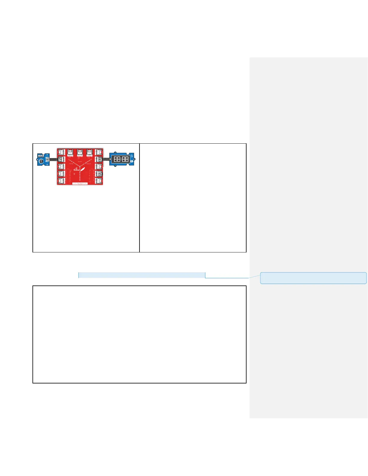
Connections:
Plug the Grove-Rotary Angle Sensor module
into Analog Grove connector J6 on the
BoosterPack. This will link the SIG pins of the
potentiometer to pin 24 of the LaunchPad.
Plug the Grove-4-Digit Display module into
Grove connector J14 on the BoosterPack.
This will link the 2 SIG pins of the 4 digit
module to pins 38 (DIO) & 39 (CLK) of the
LaunchPad.
CODE
This example is available here:
File > Sketchbook > LaunchPad_Kit > Grove_Modules > rotary_angle_sensor
Rotary Angle Sensor
Demonstrates analog input by reading an analog sensor on J16 of the Grove Base
BoosterPack. The speed of the red LED on the LaunchPad will change depending on the
position of the potentiometer knob. This example will also display the analog reading value on
the Grove 4-digital display.
The circuit:
* Potentiometer attached to pin 24 (J6 on Grove Base BoosterPack)
* center pin of the potentiometer to the analog pin
* one side pin (either one) to ground
* the other side pin to VCC (3.3V)
* Note: Because of unstable of the voltage, the value of the rotary angle sensor
varies slightly from run to run even you don't touch it.
批注 [14]: Update file path and add header files to
sketch folder