Example - 07 : Turning on an LED by Sound (Sound Sensor)
WHAT ARE WE DOING HERE?
This example program shows how to use the sound sensor (microphone). When the incoming
sound amplitude exceeds a threshold, we will turn an LED on for 1 second.
THE CIRCUIT
Parts:
● Grove-Sound Sensor x1
● Grove cable x1
● Grove-Base BoosterPack x1
● LaunchPad Development Kit
Connections:
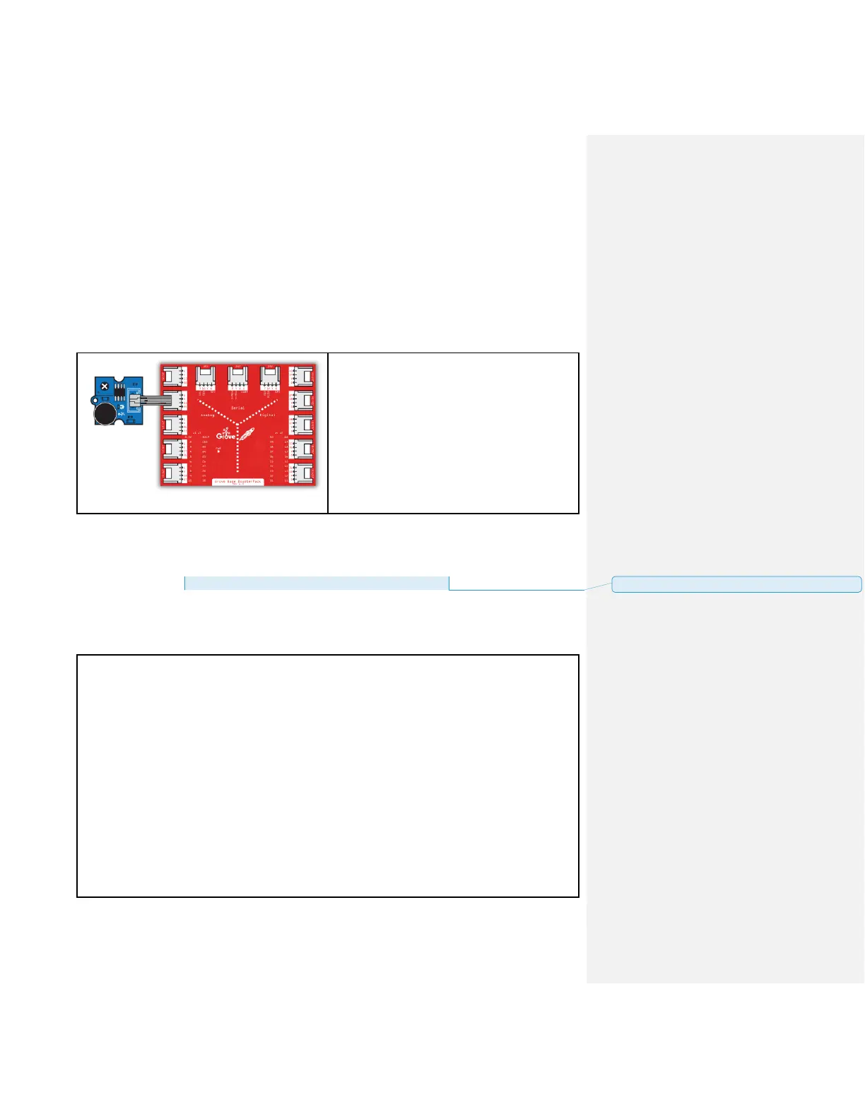
Plug the sound sensor module into Analog
Grove connector J6 on the BoosterPack. This
will link the SIG pin of the microphone to pin
24 of the LaunchPad.
CODE
This example is available here:
File > Sketchbook > LaunchPad_Kit > Grove_Modules > sound_sensor
Note that depending on your LaunchPad’s ADC resolution, you may have to adjust the
THRESHOLD_VALUE for the desired sensitivity. For 8-bit ADC 200 is acceptable, for 10-bit
ADC 500, and for 12-bit 3000 is good.
Sound Sensor
A simple program demonstrate sound sensor senses a sound that is up to the threshold you
set
in the code, the LED is on for 1s.
The circuit:
* sig pin of the sound sensor to the analog pin 24 (J6 plug on Grove Base BoosterPack)
* one side pin (either one) to ground
* the other side pin to +VCC
* LED anode (long leg) attached to RED_LED
* LED cathode (short leg) attached to ground
* Note:
This example code is in the public domain.
批注 [16]: update file path