Parts:
● Grove-Temp & Humidity Sensor x1
● Grove-4-Digit Display x1
● Grove cable x2
● Grove-Base BoosterPack x1
● LaunchPad Development Kit
Connections:
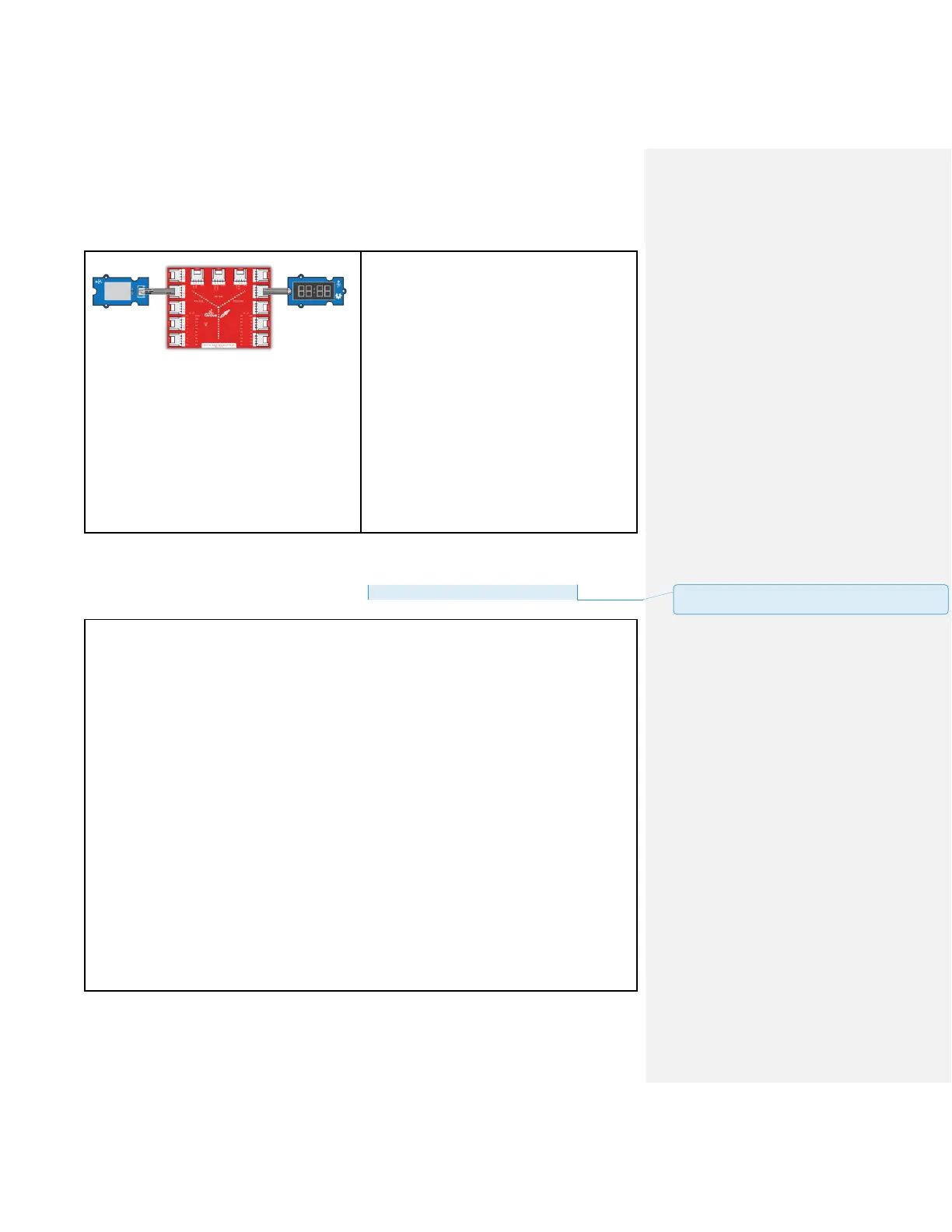
Plug the Grove-Temp & Humidity Sensor
module into Analog Grove connector J6 on
the BoosterPack. This will link the SIG pin of
the ultrasonic sensor to pin 24 of the
LaunchPad.
Plug the Grove-4-Digit Display into Digital
Grove connector J14. This will link the 2 SIG
pins (CLK & DIO) of the 4 digit module to pins
38 & 39 of the LaunchPad.
CODE
This example is available here: File > Example > LaunchPad_Kit> temp_humi_sensor
/*
Grove-Temperature-Humidity Sensor
Read value from grove-temperature-humidity sensor then display on grove-4-digital-display
The circuit:
* 4-digital-display attached to pin38 & pin39 (J14 plug on Grove Base BoosterPack)
* sig pin of the Grove-Temperature-Humidity Sensor to the analog pin 24 (Grove connector
J6)
* one side pin (either one) to ground
* the other side pin to +VCC
* LED anode (long leg) attached to RED_LED
* LED cathode (short leg) attached to ground
* Note: Put your hands on Grove-Temperature-Humidity Sensor, both of the value
will rise.
4-digital-display:
|--------------------------|
| temperature : humidity |
|--------------------------|
This example code is in the public domain.
http://www.seeedstudio.com/wiki/Grove_-_Temperature_and_Humidity_Sensor_Pro
批注 [21]: update file path and add header files to
sketch folder
 Loading...