Smart Positioner
SP740 Series
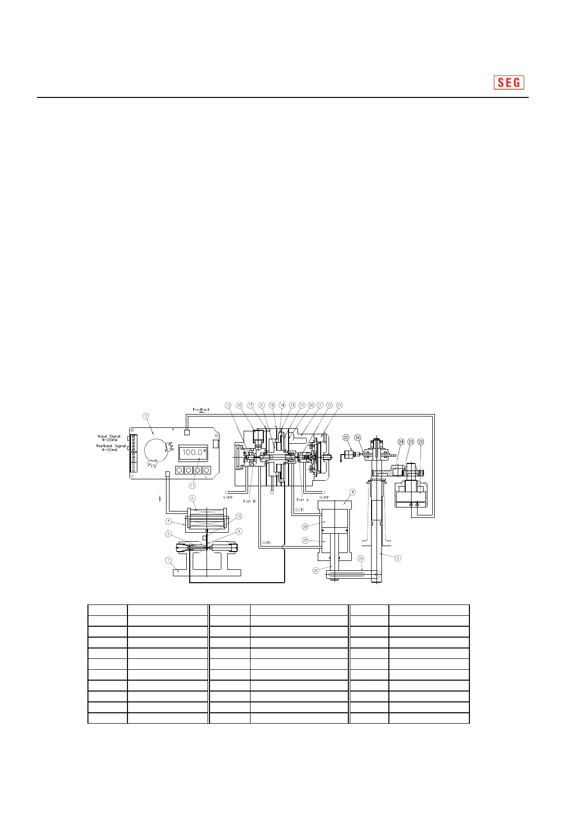
2.7 Principle of Operation
Once Control PCB(3) receives an input signal(4~20mA), the input current is delivered to coil(6)
of Torque Motor(1), from which magnetic force is generated in core(7) and the force and polarity
difference with a permanent magnet moves nozzle flapper(9), by which nozzle(8)and nozzle flapper
(9) are far isolated, lowering the pressure of nozzle pressure chamber and finally generating
the difference of pressure with the pressure chamber(14).
Therefore, spool(31) pushes poppet A(12), opening port A; OUT1 output is connected to lower cylinder
(28) while upper cylinder is connected to exhaust pipe, raising piston rod(30). Lever (29) delivers a motion
to Output Shaft(5), operating Pinion(23) and Gear(24) and rotating potentiometer(22), from which
the resistance is fed back to control PCB(3). The feedback value is compared to the input value and
calculated accordingly; if any difference is found, a changed input current is delivered to coil (6)
of Torque motor(1) . so to be properly located while repeating till it is balanced.
On the contraray, if input current is lower, Nozzle Flapper(9) blocks Nozzle(8) so that the pressure
in the nozzle pressure chamber(15) rises, spool(31) pushes poppet B(13)according to the difference
of pressure, opening port B while OUT2 output is connected to upper cylinder(27), and the lower
cylinder(28) is connected to exhaust pipe, lowering piston rod(30). Likewise, lever(29) delivers a motion
to shaft(5), operating pinion(23) and gear(240), rotating position transmitter(22) and finally delivering
the resistance to control PCB(3)
10/40
Fig : 2-3 Principle of operation
10/40
 Loading...