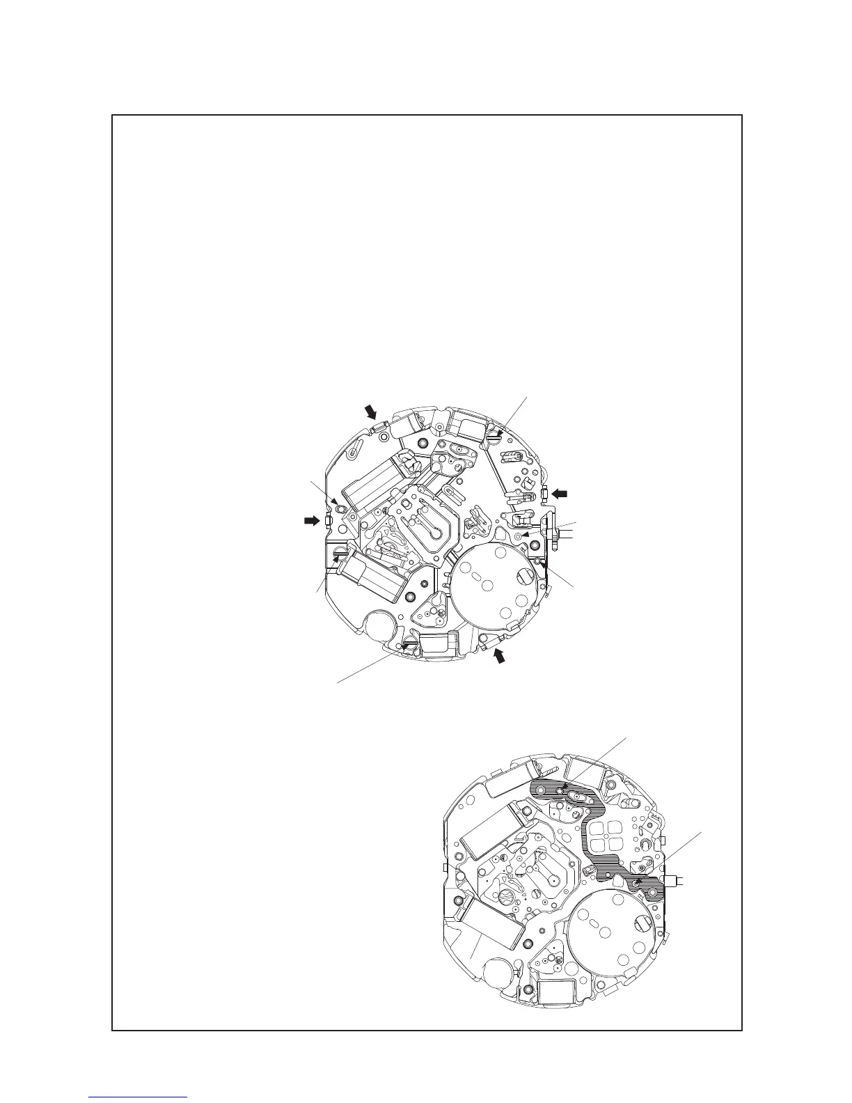
㉗ CIRCUIT BLOCK COVER
• Disassembling
1. Loosen the 3 CIRCUIT BLOCK COVER SCREWs.
2. Release the 4 hooking portions of the CIRCUIT BLOCK COVER (indicated by the arrows in the
illustration below.)
• Assembling
1. Have the four hooking portions of the CIRCUIT BLOCK COVER (indicated by the arrows in the
illustration below) catch the movement securely. In doing so, check if the circuit block is set properly
to guide posts “a” and “b,” and reset it in position if necessary.
2. Tighten the 3 CIRCUIT BLOCK COVER SCREWs. When tightening the screws, take care not to cut
the coil.
c
b
a
SCREW
SCREW
SCREW
㉘ CONDUCTING PLATE
• Assembling
Put the CONDUCTING PLATE on the CIRCUIT
BLOCK as shown in the illustration, and secure
it with the 2 guide posts.
GUIDE POST
GUIDE POST
TECHNICAL GUIDE
Cal. V172A/V174A
15/25