TECHNICAL GUIDE
Cal. V172A/V174A
21/25
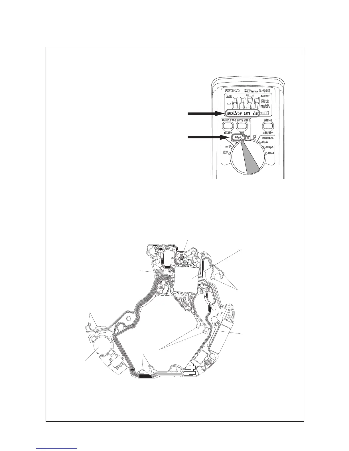
* When measuring the current consumption using
the SEIKO digital multi-tester (S-860), use the
range of 40 μA of SUPPLY V (=1.55 V) & GATE
TIME (2S).
* Avoid exposing the CIRCUIT BLOCK to direct
light in order to obtain the correct measurement.
2) Wait until a stable measurement becomes available. It usually takes 30 seconds to a few minutes
for getting a stable measurement.
3) Make sure that the read value is less than 0.30 μA.
Note:
In case the measurement of the current consumption for a whole movement exceeds the standard
value but the measurement for the circuit falls below the standard value, a problem in the gear train
mechanism is suspected. Please disassemble and overhaul the movement and measure the current
again.
C一MOS-IC
COIL OUTPUT TERMINAL
UPCONVERTER COIL
CRYSTAL OSCIL ATOR
<How to measure the current consumption for the CIRCUIT BLOCK alone>
1) Connect each probe to the appropriate (-) and (+) input terminal of ㉚ CIRCUIT BLOCK (please refer
to the "Structure of the CIRCUIT BLOCK" below).
[Structure of the CIRCUIT BLOCK]
INPUT TERMINAL (+)
INPUT TERMINAL (-)
COIL OUTPUT TERMINAL
COIL OUTPUT TERMINAL


 To Next Page