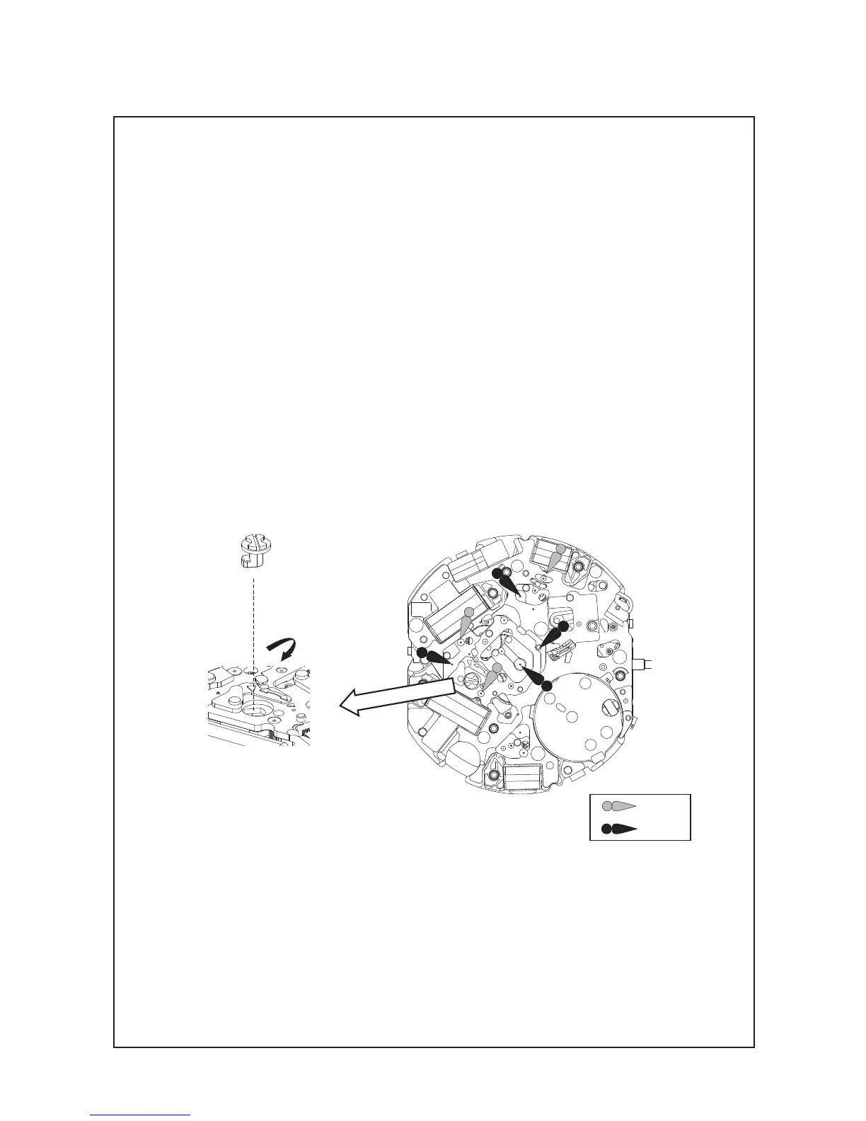
㉜ PIN FOR TRAIN WHEEL BRIDGE
• Disassembling
Turn the PIN FOR TRAIN WHEEL BRIDGE counter clockwise by 90 degrees, and loosen it.
• Reassembling
Set the PIN FOR TRAIN WHEEL BRIDGE as shown in the illustration, and tighten it by turning
clockwise by 90 degrees. (Refer to the Fig. 1.)
<Lubrication>
After fastening the PIN FOR TRAIN WHEEL BRIDGE, lubricate the upper part of the pivots of the
following parts (refer to the Fig. 2):
• 4ROTORs:AO-2
• MINUTEWHEEL:AO-3
• SMALLSECONDHAND:AO-3
• MINUTECOUNTINGWHEEL:AO-3
• ALARMMINUTEWHEEL:AO-3
• 1/5-SECONDCOUNTINGWHEEL:AO-3
AO2
AO3
TECHNICAL GUIDE
Cal. V172A/V174A
17/25
㉝ TRAIN WHEEL BRIDGE
• Assembling
1. Check the setting positions of the WHEELs and ROTORs carefully. Be sure to check that lower
pivot of rotors are set to the MAIN PLATE properly.
2. Pull out the SETTING STEM to the 1st click position.
3. Install the TRAIN WHEEL BRIDGE without pushing hardly. If the BRIDGE can not be installed
smoothly, recheck the setting position of WHEELs and ROTORs as some parts may be set in
the wrong position.
<Setting position>
Refer to the illustration in the next page.
Fig. 1
Fig. 2