! Positioning the probe:
For optimum probe reading, position it perpendicular to the tubing (probe cable extracted upward).
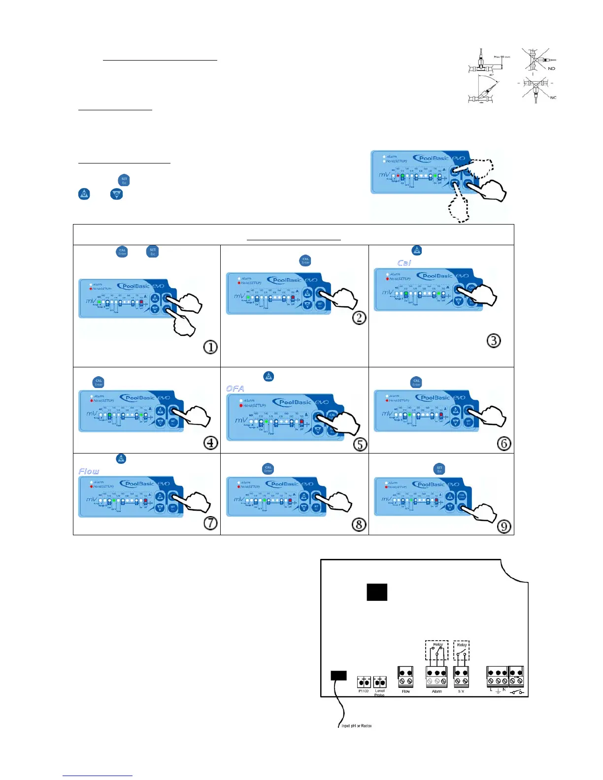
! The probe’s angle of inclination must never exceed 45° from vertical.
Electrical wiring:
Connect the power supply cable to the mains and the servocontrol pre-wired cable to the auxiliary
contact of the filter box (230 Vca)
Set Point adjustment
Keep the key pressed down and set the desired value using the
and keys.
Adjustment (Setup)
Press the and keys
(simultaneously) for 5 seconds to
enter the SETUP programme
Choose the Redox measurement
scale using the key
Press the key twice to progress
to the
C a l
light
Block or authorise calibration using
Press the key to progress to the
O F A
light (see page 4)
Block or authorise the OFA alarm
using the key
Press the key to progress to the
F l o w
light (see page 4)
Block or authorise the Flow function
Confirm and exit the adjustment
Confirm and exit the adjustment
key
Wire Connection:
1) Input Redox Probe
2) Input Temperature Probe (PT100)
3) Input Level Probe (Product Tank
4) Input Flow Rate (High Voltage 230 Vac)
5) Output Relay Alarm remote (Dry contact, Relay
250 Vac 10 A)
6) Output Relay Drive Solenoid Valve (Dry contact,
Relay 250 Vac 10 A)
7) Power Supply 230 Vac
8) Switch Power Supply