2
SEL-735 Quick-Start Guide Date Code 20131015
SEL-735 Overview
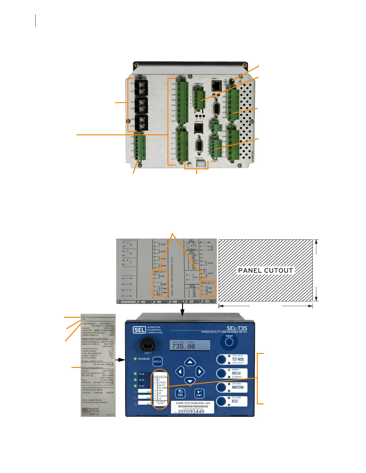
B. Rear-Panel Layout
Removable connectors allow easy wiring for PT circuits, I/O, communications, and the auxiliary power
supply. The CT circuits require ring terminals for safety.
Figure 2 Rear-Panel Layout
C. Labels and Dimensions
Figure 3 Labels and Dimensions
CT Board
Ia, Ib, Ic
Main Board
Ethernet
EIA-232
IRIG-B
EIA-232/485
Power Supply Board
2 Digital Inputs
3 Digital Outputs
Communications Board
(Expansion Slot #1)
EIA-485
Telephone Modem
EIA-232
Sealing
mechanism
PT Board
Va, Vb, Vc, Vn
Ground Terminal
I/O Board
(Expansion Slot #2)
4 Digital Inputs
4 Digital Outputs (solid-state
or electromechanical)
or
4 Analog Outputs
4 Digital Solid-State Outputs
7.36 in (187.0 mm)
5.47 in (139.0 mm)
The cutout dimensions
for the horizontal and
vertical meter chassis
are identical. The
vertical chassis is
designed to fit into
existing panel cutouts
with an optional
retrofit bezel.
Part No.
Serial No.
Auxiliary
power supply
input voltage
Compliance
marks
ANSI Configuration Label
FM: Form designation
CL: Current class
V: Rated voltage
W: Wires
Hz: Frequency (hertz)
TA: Test amperes
Kt: Watt-hour meter test
constant
Control input voltages
The top and side labels depict important information,
including auxiliary power supply input voltage.