12
SEL-735 Quick-Start Guide Date Code 20131015
Human-Machine Interface (HMI)
7. Scaling and Display Settings
The VOLT_SCA, POWR_SCA, ENRG_SCA, and PRI_SCA configuration settings affect how the meter
reports quantities to communications channels and internal and external interfaces. The meter always
reports LDP1 energy values as change-over-internal (COI) in primary kilo units to ensure compatibility
with MV-90 software. All other LDP recorders report energy as defined by the scaling settings.
8. Communications and Protocol Settings
The SEL-735 supports the communications protocols listed in Table 2. The Ethernet port supports six
simultaneous communications sessions, including five DNP3 LAN/WAN sessions. Port 4 supports three
communications options, but only one is available at a time.
To change the communications parameters, click on the desired communications port followed by
Communications in the
ACSELERATOR QuickSet settings editor tree.
Table 2 Available Communications Protocols
Protocols Ethernet (Port 1
a
)
a
Additional cost option.
Serial: EIA-485, Modem, and
EIA-232 (Port 2, Port 3, Port 4
a
)
Front Port (Port F)
SEL ASCII •
••
MODM
•• •
Modbus RTU
••
Modbus TCP
•
DNP3
•• •
IEC 61850
•
9. Send and Save Configuration Settings
After completing all configuration settings in ACSELERATOR QuickSet, save and send them as detailed
in Section IV.
ACSELERATOR QuickSet SEL-5030 Software.
V. Human-Machine Interface (HMI)
The ACSELERATOR QuickSet HMI displays
instantaneous meter information, captures reports,
and allows test and control of the SEL-735. To
access the Meter and Control interface, choose Tools
> HMI > HMI in the main
ACSELERATOR QuickSet
window.
To maneuver through the windows, click on the HMI
tree-view list until the required display appears on
the right-hand side. Press F1 in the HMI window to
view help on each interface.
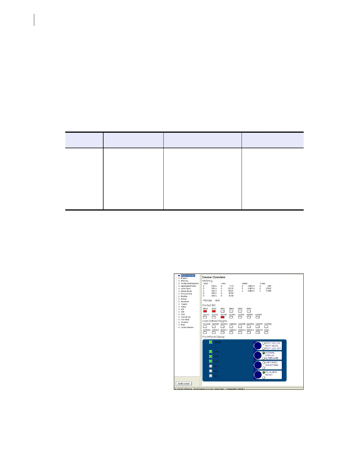
A. Device Overview
The Device Overview window emulates the
front-panel interface of the SEL-735 and
updates approximately every second. This
window displays instantaneous metering
information, and contact I/O and front-panel
LED status.
Figure 19 Device Overview Window