13
Date Code 20131015 SEL-735 Quick-Start Guide
Human-Machine Interface (HMI)
B. Phasors
Phasor diagrams are a powerful troubleshooting tool.
Technicians and engineers can quickly determine and resolve
wiring issues at a glance. This section contains phasor diagrams
from three example installations. Example 3 depicts a phasor
diagram from a properly wired installation. Example 4 and
Example 5 depict the most common wiring issues.
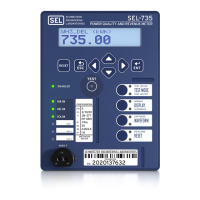
Figure 20 Correct Phase Rotation
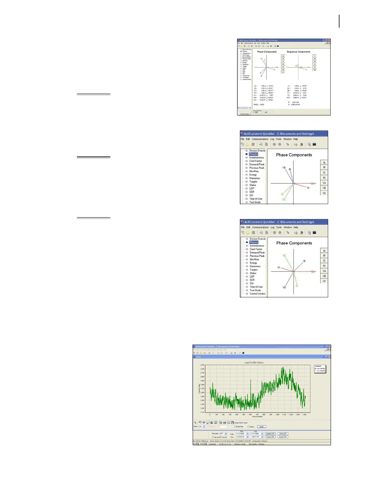
Figure 21 Incorrect Phase Rotation
Figure 22 Reversed CT Connections
EXAMPLE 3 Correct Phase Rotation
Figure 20 illustrates a balanced, three-phase, ABC rotation
installation with lagging power factor. Study the phasors in the
counterclockwise direction and note that they read as A-B-C.
The SEL-735 registers Watt-hours delivered for this condition.
Use the Phase Rotation button at the bottom of the screen to
switch phasor calculation reference between clockwise ABC and
counterclockwise ACB phase rotation. Click the buttons to the
right of the phasor quantities to hide individual phase vectors.
EXAMPLE 4 Incorrect Phase Rotation
Figure 21 illustrates the phasor diagram of a balanced, three-
phase installation with lagging power factor and two swapped
phases. Note that the phasor diagram reads counterclockwise
A-C-B. This phasor response indicates that the VB/VC and IB/IC
connections are swapped. The system responds with
unexpected ACB phase rotation instead of the IEEE standard
ABC rotation. The SEL-735 still registers energy correctly, but
the power quality functions will not operate correctly.
EXAMPLE 5 Reversed CT Connections
Many times CT polarity convention varies from site to site,
which can lead to reversed CT connections. The top label of
the SEL-735 indicates CT polarity convention with a dot that
denotes current flow out of the instrumentation transformer
and into the SEL-735 CT terminal.
Figure 22 illustrates the phasor diagram of a balanced, three-
phase installation with lagging power factor and reversed IA,
IB, and IC connections. Note the abnormal position of the phase
current with respect to their phase voltages. The SEL-735
incorrectly registers Watt-hours received for this condition.
C. LDP and SSI
The ACSELERATOR QuickSet HMI displays Load Profile and Voltage Sag/Swell/Interruption (VSSI) reports.
To capture any of these reports, select the required date range and click Export.
1. Load Profile (LDP)
The SEL-735 adds an entry to the load
profile recorder at the interval set by the
LDAR setting. This entry contains the time
stamp, the present value of the selected
LDLIST analog quantities, and a checksum.
2. Voltage Sag/Swell/Interruption
(VSSI)
The SEL-735 records voltage sags, swells,
and interruptions with 1 ms accuracy.
Enable and configure VSSI in the Voltage
Sag/Swell/Interruption Settings window of
ACSELERATOR QuickSet.
Figure 23 LDP Graph in HMI
 Loading...