Do you have a question about the Selco WF 109 and is the answer not in the manual?
Specifies environmental conditions for safe equipment use, including temperature, humidity, and location.
Details protective measures for users and bystanders against arc rays, sparks, noise, and moving parts.
Advises on protection from welding fumes, gases, and powders, including ventilation and masks.
Outlines measures to prevent fires and explosions during welding operations.
Provides critical guidance on preventing electric shocks during operation and maintenance.
Discusses the effects of electromagnetic fields and potential interference with medical devices.
Explains the Ingress Protection (IP) rating of the equipment against solids and liquids.
Provides instructions and precautions for safely lifting, transporting, and unloading the equipment.
Details the rules for correctly positioning the equipment for optimal use and safety.
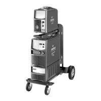
Explains how to connect the SELCO mobile units, emphasizing low voltage power.
Details the connection procedures for MIG/MAG welding, including power and signal cables.
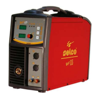
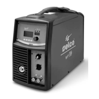
Introduces the WF 109 wire feed unit as part of a complete MIG/MAG welding system.
Describes the functions and displays of the front control panel for system operation.
Explains the system checks performed upon startup and the gas test procedure.
Details the automatic saving of welding parameters and how to manage data differences.
Describes the test screen functions available when the side panel is open, inhibiting welding.
Explains the main screen interface for controlling the system and viewing welding process settings.
Allows selection and regulation of commonly used welding parameters via an intuitive menu.
Allows electronic regulation of series inductance to adjust arc characteristics.
Enables the "Double Pulsed" function and allows pulsation amplitude regulation.
Allows regulation of the impulse repetition cycle for fine-tuning welding.
Regulates secondary pulsation level voltage for improved arc stability.
Adjusts wire burn time to prevent sticking at the end of welding.
Adjusts wire feed speed before striking for softer starts and less spatter.
Sets and adjusts gas flow before striking the arc for proper torch filling.
Sets and adjusts gas flow at the end of welding to protect the weld pool.
Enables "spot welding" process and establishes welding time.
Sets warning and guard limits for accurate control of welding phases.
Controls guard limits with adjustable delay relative to arc striking.
Allows manual setting and regulation of individual welding parameters.
Enables pre-set synergic curves and allows initial settings to be changed.
Allows storage and management of welding programs and saving current settings.
Provides functionality to cancel programs and add descriptions.
Allows personalization of parameters displayed on the main screen.
Enables personalization of parameters displayed in the quick choice menu.
Allows personalization of parameters displayed on the 7-segment display.
Defines warning thresholds for main measurable parameters.
Defines alarm thresholds that can block operations.
Displays the minimum levels for parameters within guard limits.
Displays the maximum levels for parameters within guard limits.
Shows the specific code for the active alarm.
Describes the category or nature of the alarm.
Lists various alarm codes and their corresponding issues for problem diagnosis.
Indicates the port for connecting the main power cable.
Indicates the port for connecting the signal cable.
Identifies the connections for the cooling liquid system.
Identifies the socket for connecting external Remote Controls.
Identifies sockets for connecting Push/Pull external devices.
Indicates the socket for the cooling liquid connection.
Explains how remote controls activate power source controls and vice versa.
Describes the RC 100 remote control for managing welding current and voltage.
Describes the RC 200 remote control for managing all available parameters.
Describes the RC 180 remote control for changing output current without interruption.
Details the digital MIG/MAG torches and their controllable parameters.
Emphasizes routine maintenance by qualified personnel and safety precautions.
Lists causes and solutions for the system not welding.
Identifies common wire feeder failures and their remedies.
Addresses issues causing irregular wire feeding and their solutions.
Details causes and solutions for incorrect welding output power.
Lists causes and solutions for faulty wire feeder issues.
Identifies issues with faulty potentiometers or encoders for current adjustment.
| Brand | Selco |
|---|---|
| Model | WF 109 |
| Category | Welding System |
| Language | English |