Do you have a question about the Selco WF 115 XP and is the answer not in the manual?
Explains the meaning of each item on the WF rating plate across multiple languages.
Refers to diagrams and schematics that illustrate the internal workings and connections of the welding equipment.
Lists and identifies various connectors used in the welding system.
Provides a list of spare parts for the welding equipment, often with part numbers and descriptions.
Details safe operating conditions, temperature, humidity, and altitude limits for the equipment.
Covers personal protective equipment and safety measures for operators and bystanders during welding.
Explains hazards from welding fumes and gases and necessary ventilation and respiratory protection.
Outlines precautions to prevent fires and explosions, including clearing the work area and handling flammable materials.
Provides guidelines for the safe storage and use of gas cylinders, including securing them and avoiding heat sources.
Details measures to prevent electrical shock, such as proper insulation, earthing, and avoiding contact with live parts.
Discusses the generation of electromagnetic fields by welding equipment and potential interference with electronic devices.
Explains the equipment's Ingress Protection (IP) rating (IP23S) for protection against solids and liquids.
Instructions on safely handling and moving the equipment, including weight considerations and handling procedures.
Guidelines for placing the equipment in a suitable location, ensuring access, ventilation, and stability.
Details on connecting power supply, signal cables, gas hoses, and cooling water pipes to the equipment.
Step-by-step guide for setting up the welding machine, including connecting the MIG torch and wire feeder.
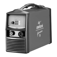
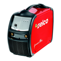
Introduces the UNISTEP Series MIG/MAG welding systems and their features like constant voltage and synergy mode.
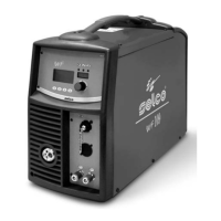
Identifies and explains the function of various controls and indicators on the equipment's front panel.
Details how to access and adjust system parameters for enhanced control and accuracy.
Lists and explains various alarm codes displayed by the equipment, indicating potential issues or faults.
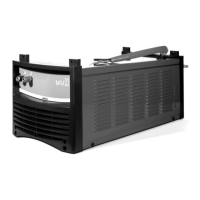
Identifies and describes the connectors and fittings located on the rear panel of the equipment.
Details the various connectors and ports available on the equipment's sockets panel for external connections.
Troubleshooting steps for when the system does not weld, covering causes like faulty trigger or overheating.
Addresses issues with incorrect output power, suggesting parameter resets or checking potentiometers.
Solutions for wire feeder malfunctions, including checking the trigger button, rolls, and the feeder unit itself.
Explains causes of excessive spatter and suggests adjusting welding parameters or arc regulation.
Discusses reasons for insufficient weld penetration and recommends adjustments to welding mode or travel speed.
Identifies causes of blowholes in welds, such as insufficient shielding gas or incorrect welding mode.
Provides solutions for wire sticking issues, including parameter adjustments and torch angle.
Explains how to avoid undercuts by adjusting welding parameters, oscillation speed, and travel speed.
Covers causes of oxidation in welds, primarily insufficient gas protection and workpiece cleanliness.
Addresses porosity in welds, recommending proper gas flow, workpiece cleaning, and filler material quality.
Explains causes of hot cracks in welds, such as incorrect parameters, workpiece cleanliness, and filler material condition.
Explains the basic components and function of a MIG system and the current transfer process to the workpiece.
Describes the two main MIG welding metal transfer mechanisms: SHORT-ARC and SPRAY-ARC.
Discusses the impact of voltage and wire feeding speed on weld appearance and bead dimensions.
Details the types of shielding gases used in MIG-MAG welding (CO2, Argon, Helium) and their effects.
| Welding Process | MIG/MAG |
|---|---|
| Input Voltage | 230V |
| Frequency | 50/60 Hz |
| Welding Current Range | 20-115A |
| Wire Diameter | 0.6 - 0.8 mm |
| Duty Cycle | 60% at 115A |
| Electrode Diameter Range | 1.6-3.2 mm |
| Insulation Class | H |