MI00035 -E9 ENGLISH - 3/8
ELECTRICAL CONNECTIONS
POWER SUPPLY
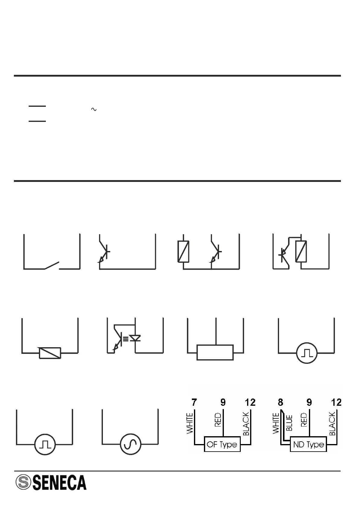
INPUTS
We recommend using shielded cables for the connection of the signals; the shield must
be connected to a designated ground connection for the instrurmentation. We also
discourage passing the wires near the power supply cables for inverters, motors, or
induction ovens, etc.
19 ÷ 28 V
19 ÷ 40 V=
2
3
The power supply voltage must be between 19 and 40 V DC
(polarity not important), 19 and 28 V AC; also see the section
entitled “INSTALLATION RULES”.
The upper limits must never be exceeded at the risk of
creating serious damage to the module.
The power supply source must be protected against all risk of
module malfunction
by the use of an well sized fuse.
8
Contact / Reed
11
Photo-electric
7 9 10
NPN (2 wires)
8 11
+ -
NPN 24V (3 wires)
9 8 11
+ s -
NAMUR
7 9
-
+
PNP 24V (3 wires)
7 9 11
s + -
“HALL” sensor
7 9 12
S +
-
7
Input 24V
11
+
7
TTL input
12
+
10
Variable reluctance
12
+
>100mV
Turbine or oval gear “AICHI”