Do you have a question about the Seneca Z111 and is the answer not in the manual?
Identifies specific operating conditions considered demanding for the module's performance, requiring careful consideration during installation.
Details required voltage and current specifications for powering the module, emphasizing adherence to limits.
Diagrams and specifications for various types of input signals the module can process, covering different sensor types.
Illustrates the voltage and active current output signals of the Z111 module with corresponding terminal references.
Instructions for setting the filter using dip-switch SW6 to stabilize output signals when input frequency is unstable.
Table detailing response times and LED error indication for different input frequency range settings.
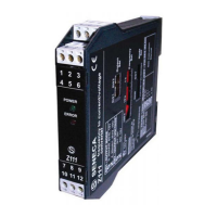
The Z111 is a versatile frequency-to-current/voltage converter designed to interface with a wide array of industrial sensors, providing a standardized output signal for control and monitoring applications. Its primary function is to convert incoming pulse signals from various sources into a proportional analog current or voltage output. This capability makes it an essential component in systems requiring the measurement and control of rotational speed, flow rates, or other frequency-dependent parameters.
One of the key usage features of the Z111 is its broad compatibility with different sensor types. It can accept inputs from mechanical contacts, reed switches, and a variety of transistor-based sensors including NPN (2-wire and 4-wire) and PNP (3-wire) types, accommodating both 24V DC power supplies. Furthermore, it supports specialized sensors such as Namur, photoelectric, and "HALL" sensors, as well as variable reluctance sensors and 24V and TTL pulse sources. This extensive input flexibility ensures that the Z111 can be integrated into diverse industrial environments without requiring multiple specialized converters.
The device offers a wide range of selectable full-scale frequencies, from a very low 1 mHz up to 9.99 KHz. This allows users to precisely match the converter's range to the specific application requirements, ensuring accurate and responsive measurements. Setting the full-scale frequency is made straightforward through the use of rotating switches, simplifying the configuration process.
Another significant usage feature is the ability to select the output mode. The Z111 supports several standard analog output ranges, including 0/4-20 mA, 0/1-5V, and 0/2-10V. This selection is easily accomplished using dip-switches, providing flexibility to integrate with various control systems and data acquisition devices that expect different signal types.
For applications where input signals might be unstable or noisy, the Z111 incorporates a feature to set the number of pulses for calculating the pulse average. This is particularly useful when dealing with sensors that provide cyclically unstable frequencies, such as those monitoring irregularly spaced events (e.g., bolts on a wheel). By averaging over a defined number of pulses, the device can provide a much more stable and reliable output signal, preventing erratic readings and improving system performance. The pulse average setting is configured via dip-switches, allowing users to tailor the response to their specific signal characteristics.
The Z111 also includes practical indicators for operational status. Front panel LEDs provide clear indications of power supply presence and out-of-scale errors. These visual cues are invaluable for quick troubleshooting and monitoring the device's health, allowing operators to identify issues at a glance.
Regarding maintenance and installation, the Z111 is designed for mounting on DIN 46277 guides in a vertical position. Proper ventilation is crucial for long-lasting and optimal performance, so care must be taken to avoid obstructing ventilation slots with cable raceways or other objects. It is recommended to install the modules in the lower part of the panel to avoid heat generated by other equipment. The device features 3-point insulation, rated at 1500V AC, which enhances safety and protects against electrical interference, contributing to its robust design.
Special considerations are outlined for "taxing work conditions," which include elevated power supply voltages, providing power to sensor inputs, and using the active current output. In these scenarios, especially with higher panel temperatures, specific separation distances between paired modules may be required to ensure adequate cooling and prevent overheating.
For variable reluctance type inputs, internal jumpers must be selected. The manual provides clear instructions on how to access and set these jumpers, which involves removing the container's lateral closing panel. The device is supplied with internal jumpers set for standard inputs, indicating that a specific configuration step is needed only when using variable reluctance sensors.
Hysteresis calibration is a maintenance feature specifically for variable reluctance inputs. This process involves connecting a tester to the device's output, providing an input signal, and using a screwdriver to adjust a trimmer. The goal is to achieve a stable input reading, with an additional clockwise rotation to ensure a sufficient calibration safety margin. This detailed calibration procedure ensures accuracy for this specific sensor type.
A filter setting is available to stabilize the output signal when the input frequency is unstable. This filter can be activated by positioning a specific dip-switch, enhancing the reliability of the output in noisy environments. It is explicitly stated that dip-switch settings, including those for output mode, output voltage, multiplier, and pulse average, must be performed after disconnecting the module's power supply to prevent damage. This emphasizes a critical safety and maintenance protocol.
The Z111's design and features collectively aim to provide a reliable, flexible, and user-friendly solution for frequency-to-analog signal conversion in industrial applications, with clear guidelines for installation, configuration, and maintenance to ensure optimal performance and longevity.
| Device Type | Media Converter |
|---|---|
| Fiber Ports | 1 |
| Copper Ports | 1 |
| Copper Connector | RJ45 |
| Power Supply | 5V DC |
| Mounting | DIN Rail |
| Ports | 1 x Fiber, 1 x Copper |
| Fiber Connector | SC |
| Fiber Type | Multimode |
| Wavelength | 850nm |
| Connector Type | RJ45, SC |