MI00035 -E9 ENGLISH - 5/8
HISTERESYS CALIBRATION
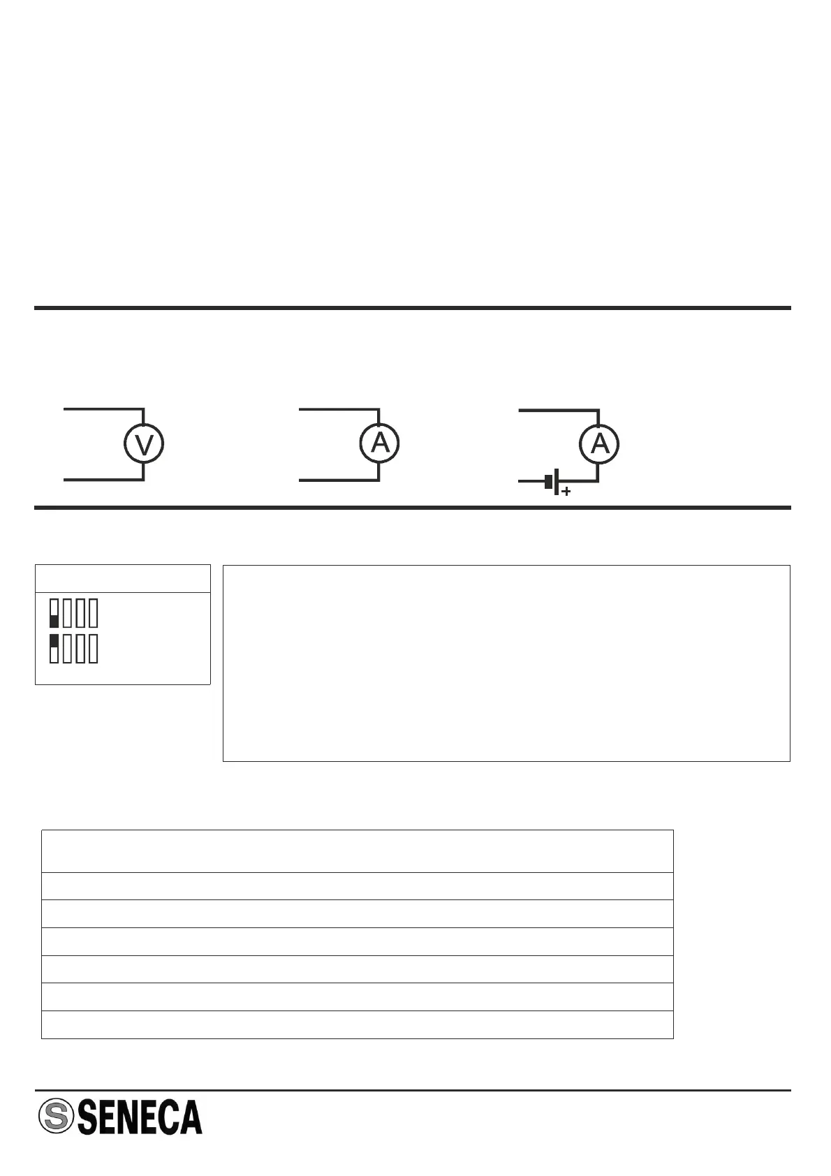
RETRANSMITTED OUTPUT
FILTER SETTING
Voltage Active current Ext. power supply current
This operation is only performed when the “variable reluctance” input is used.
For the hysteresis calibration, after first correctly setting the internal jumpers and the full-
scale frequency, a tester must be connected to the device's output (it makes no difference
whether the voltage or current output is used) and an input signal must be provided; then
using a screwdriver, rotate the hysteresis trimmer completely counter-clockwise (the
tester should indicate 0) and then the trimmer must be slowly rotated clockwise until the
tester provides a stable input reading. At this point, rotate the trimmer clockwise by around
5% in order to have a sufficient calibration safety margin.
NOTE : remember that the minimum signal amplitude is 100 mV.
1
6
+
5
4
+
1
5
+
SW6 - FILTER
Filter OFF
Filter ON
Whenever the input frequency is unstable, a filter can be set
to stabilise the output signal. In order to set this filter, position
SW6 ON dip-switch no. 1 in the position (by shifting it
upwards).
N.B.: The dip-switches must be set after first
disconnecting power supply from the module in order to
avoid damaging the module.
RESPONSE TIME
RANGE
x 0,0001
x 0,001
x 0,01
x 0,1
x 1
x 10
RESPONSE TIME
25 sec
2,5 sec
0,25 sec
0,25 sec
0,25 sec
0,25 sec
Led error after
1000 sec
100 sec
10 sec
10 sec
10 sec
10 sec