MT3401E.doc rev.0 21/05/13 Pagina 13 di 86
Detectors with 4-20mA output
Detectors with 4-20mA analog output are connected to the unit via remote 8-input modules
STG/IN8-S. The modules are connected on the panel's bus to be field mounted far from the
control panel.
A 4-20mA transmitter requires a 3-core wire for connections: 2 wires for power supply (usually
12 to 28 Vdc but refer to the gas detector technical manual) and one wire for the 4-20mA signal.
A 3x0.75mm
2
shielded wire is recommended since it can cover a 100 m distance between the
gas detector and STG/IN8-S input module.
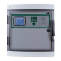
Detectors with 4-20 mA output directly connected to the unit
Scheda centrale / panel main board
Det.1
Det.2
Det.3
Det.4
Det.5
Det.6
Det.7
Det.8
S
Fig. 2.2.1 a) Connection of the 8 detectors of the control panel
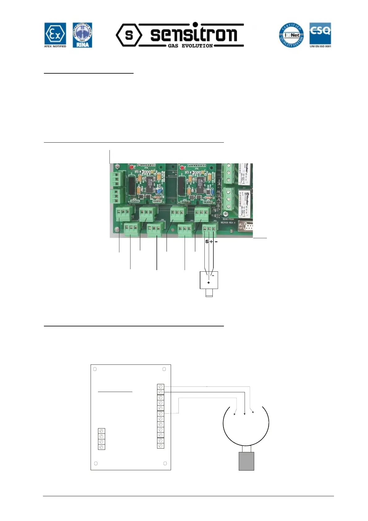
Rilevatori con uscita 4-20 mA collegati a moduli ST.G/IN8-S
The following diagram illustrates connections between a 4-20mA gas detector and a STG/IN8 S
input module. When starting the system, make sure minimum 12Vdc voltage reaches each gas
detector.
-V
I8
I7
I6
I5
+V
-V
I4
I3
I2
I1
+V
-V
B
A
+V
REMOTE INPUT
MODULE ST/G.IN8
(+V)
(-V)
(S)
Positive
Negative
4-20 mA
signal
4-20 mA
analog
gas
detector
Rilevatore
analogico
4-20 mA
MODULO INGR.
4-20 mA ST/G.IN8
Fig. 2.2.1 b) Connection of the 8 detectors of the ST.G/IN8-S module