Do you have a question about the Sensitron MULTISCAN++S1 and is the answer not in the manual?
Describes the system architecture and connectivity options for MULTISCAN++S1.
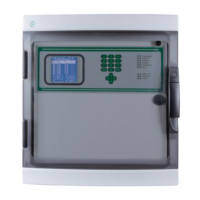
Lists the technical details of the MULTISCAN++S1 control panel and its housing.
Covers mounting the control panel and its electrical connections.
Identifies key components and provides a wiring diagram for the unit.
Details the layout of the central control board and its connectors.
Explains power connections and DIP switch configuration for communication and language.
Details connecting external gas detectors and modules to the system.
Explains connecting detectors via 4-20mA analog or RS485 digital outputs.
Describes STG/IN8-S input, STG/OUT16-S output, and STG/8REL relay modules.
Covers addressing STG/IN8-S and STG/OUT16-S modules using rotary switches.
Instructions for switching on the unit and understanding the normal operating screen.
Explains the various operational states (NORMAL, ALARM, FAULT, etc.) and general navigation.
Details states like NORMAL, ALARM, FAULT, TEST/MAINTENANCE, UNSET, EMERGENCY.
Describes how Alarms, Faults, and Emergency events are displayed and acknowledged.
Outlines user levels (Operator, Maintenance, Engineer) and main menu options.
Describes the capabilities and limitations of the Operator user level.
Covers the advanced functions available to Maintenance and Engineer users.
Navigating the event log and accessing system information and print options.
Managing system configuration through Zones, Modules, Relays, and Channels.
Defining logical zones and configuring input/output modules.
Configuring gas detector channels and output relay settings.
Covers software requirements, installation, and starting the configuration program.
Navigating the program homepage and main menu options.
Managing configuration files: creating, opening, saving, comparing.
Configuring serial port, language, user management, and communication.
Exporting reports, accessing program info, and managing configuration files.
Creating, modifying, and managing system configuration files.
Entering site details and configuring general system parameters.
Configuring system zones, modules, channels, and output relays.
| Protection degree | IP65 |
|---|---|
| Type | Control Unit |
| Power supply | 24 V DC |
| Outputs | 4-20 mA output (optional) |
| Communication | RS485 |
| Display | LCD display |