MT3401E.doc rev.0 21/05/13 Pagina 17 di 86
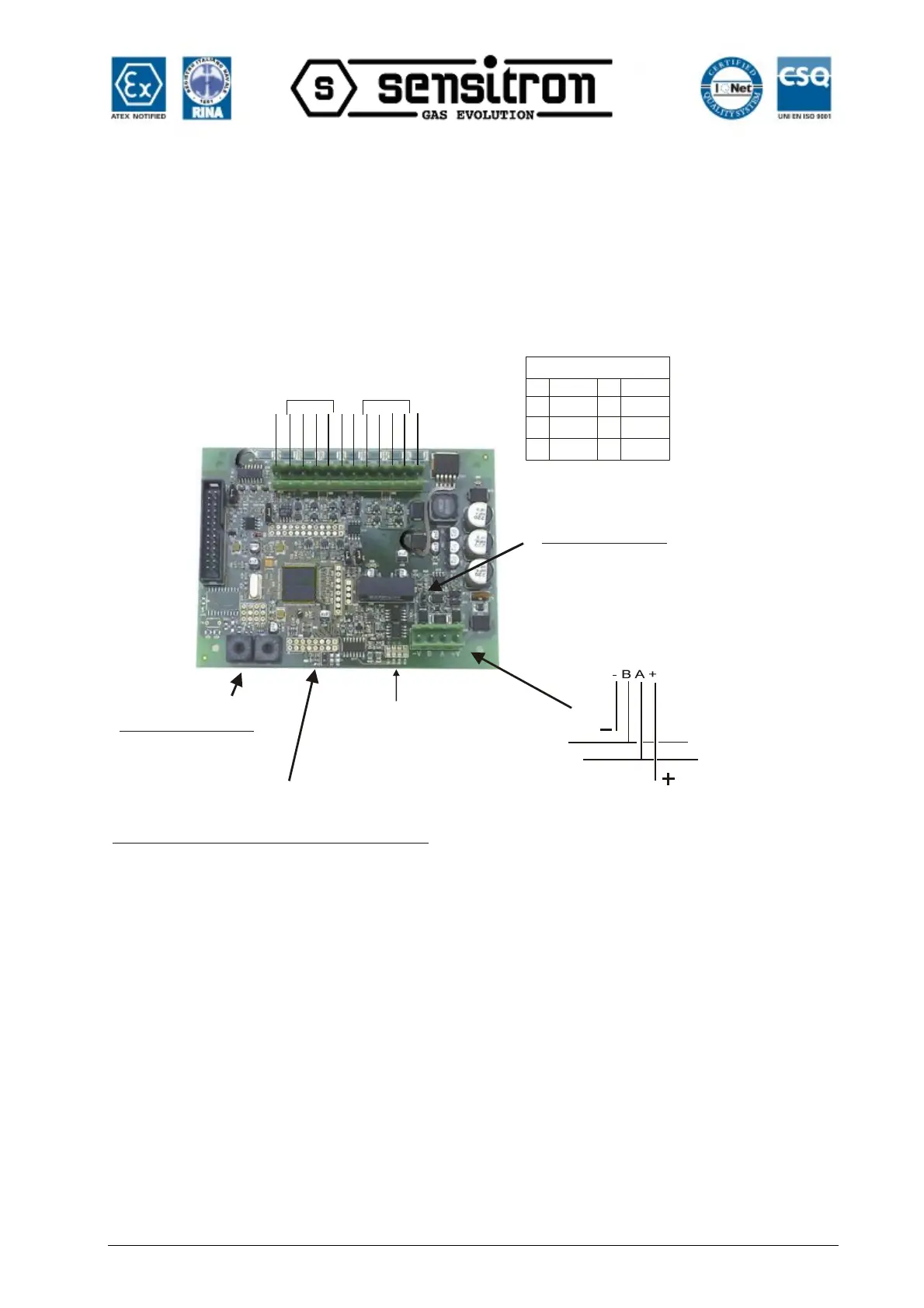
2.3) STG/IN8-S remote input module
STG/IN8-S remote modules are field mounted and are connected to the panel via
RS485 buses. They are used to connect 8 x 4-20mA analog gas detectors. Each
module must be addressed using the rotary switches on the PCB. The address must be
univocal and between 1 and 255. For the maximum number of modules, see the table at
chapter. 1- Introduction
Jumper da non manomettere
/ jumpers not to be touched
Jp1
Jp2
Jp3
Jp4
Jp9
Jp11
Jp12
Jp14
Closed 1-2
Closed
Closed
Open
Open
Open
Closed 1-2
Led
DL1: Guasto WD /WD Faul
DL2: TX Data
DL3: RX Data
DL4: RTS
Jp10
Resistenza di file linea
(EOL resistor)
Se il modulo è l’ultimo della linea chiudere Jp10
/ If the module is the last of the bus line, close JP10
A
B
Rs485 serial line
Morsettiera alimentazione e linea seriale
(Power supply and serial line)
Jp13 Communication Baud Rate setting:
Closed 115.000 bps (Multiscan++ control panel
Open 9.600 bps (old Galileo Multiscan control panel)
Jp13 Settaggio velocità comunicazione:
Chiuso 115.000 bps (Centrale Multiscan ++)
Aperto 9.600 bps (vecchia centrale Galileo Multiscan)
Commutatori rotativi
per l’indirizzo del modulo
Channels 5-8
Channels 1-4
-V
+V
-V
+V
Morsettiera rilevatori
(gas detector connections)
Open
Rotary switches for
the module address)
Fig. 2.3) ST.G/IN8-S module