EasyManua.ls Logo

Sera 620.10 - Technical Specifications; 9 Installation

Sera 620.10
20 pages
Print Icon
To Next Page IconTo Next Page
To Previous Page IconTo Previous Page
Loading...
Diaphragm Relief Valve
Operating Instructions
10
www.sera-web.com
Subject to technical modifications!
TA
48
Rev.
13
en
05/2016
8.2 Technical specifications
Type
Max. allowable operating
pressure
Set pressure p
e
Max. capacity Q
K
VS
value
[bar]
[bar]
l/h
m
3
/h
620.10
10
2,5 ... 10
200
0,26
622.10
10
2,5 ... 10
500
0,6
623.10
10
1,5 ... 10
1000
1,12
624.10
10
1,5 ... 10
2000
2,1
625.10
10
1,5 ... 10
4000
4,0
626.10
10
1,5 ... 10
7000
6,7
627.10
10
1,5 ... 10
10000
9,12
Table 05 Technical data
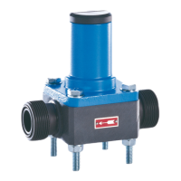
9 Installation
The cover is to be mounted vertically to the top.
The diaphragm relief valve is to be installed in such a way
that no static, dynamic or thermal loads from the supply-
or return line are transmitted to the relief valve.
Install the diaphragm relief valve near the pump and in
front of the first shut-off valve.
Diaphragm
Supply line relief valve
Shut-off valve
Bracket
Return line
Dosing pump
Fig. 06 Example of an installation
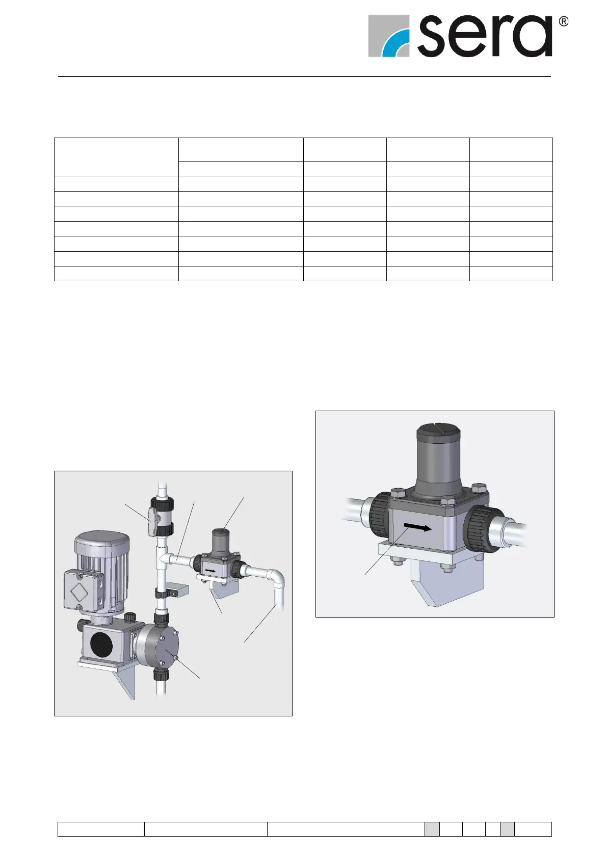
The flow direction is indicated by an arrow.
Flow direction
Fig. 07