9.1 Supply line
Keep the supply line as short as possible and lay it in such a
way that only low acceleration pressures or pressure losses
develop.
Avoid contamination and precipitations.
9.2 Return line
Keep the return line as short as possible and lay it downgrade.
Elbows are to be preferred to angles. The return line must not
be under pressure, provide for a free outlet (see Fig. 06).
Make sure that there are no shut-off valves or check valves in
the return line.
If the return line is linked to the suction line of the pump, no
check valves may be installed in the suction line.
Lay the lines in such a way that precipitations are excluded.
10 Start-up
During commissioning, observe the following:
• Open all shut-off valves that are mounted in the suction
line and pressure line (except for flushing and discharge
fittings).
• Start pump / system.
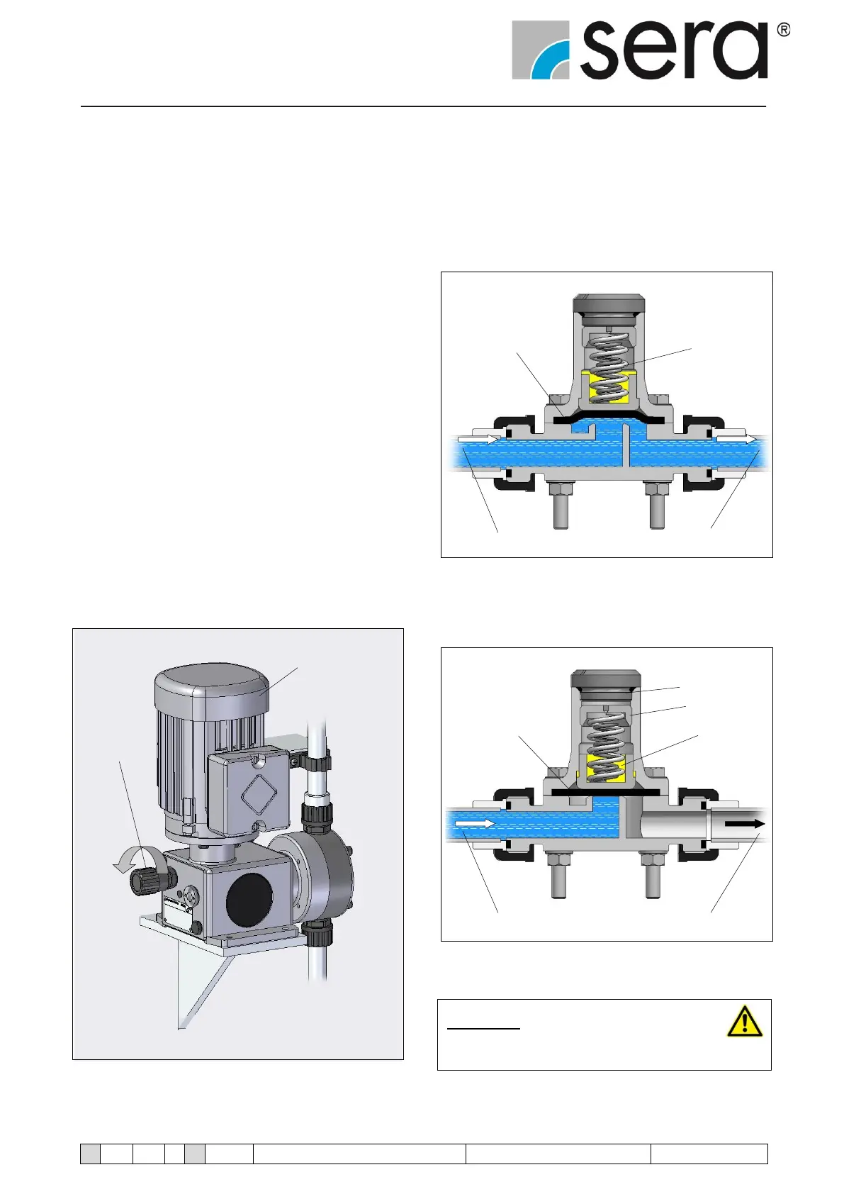
• Slowly increase the delivery rate via the stroke frequency
or stroke length adjustment to the maximum setting (see
Fig. 08).
Dosing pump
Stroke length
adjustment
Fig. 08
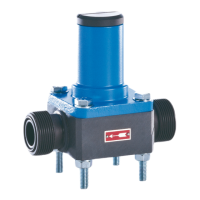
The diaphragm closes the inlet channel by the pressure spring
initial tension (= set pressure of the valve in bar).
If the medium at the diaphragm reaches the set pressure, the
diaphragm is lifted and the medium flows in the outlet channel
(see Fig. 09).
Diaphragm Damping fluid
Inlet channel Outlet channel
Fig. 09 Operational mode
The diaphragm closes the inlet channel only when the pres-
sure of the medium drops below the set pressure (see Fig. 10).
Lid
Set screw
Diaphragm Damping fluid
Inlet channel Outlet channel
Fig. 10 Operational mode
CAUTION !
The use of damping fluid is shown of the table 07
(page 16).