11 Adjustment
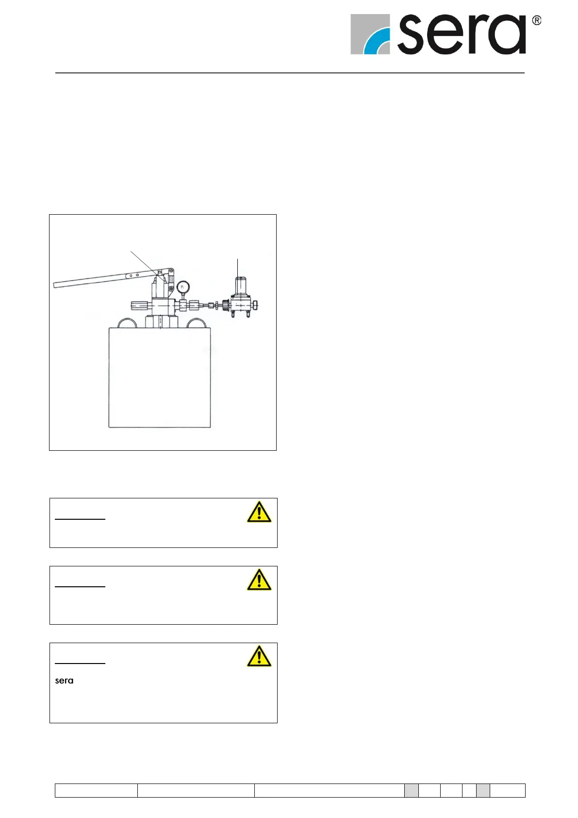
Check the set pressure by means of e.g. a pipe test pump. If
the set pressure does not match the indication on the type
plate, remove lid and correct pressure using the set screw.
• Turning counterclockwise: the set pressure reduces
• Turning clockwise: the set pressure increases
Pipe test pump Diaphragm
relief valve
Fig.11 Check
CAUTION !
The operator is obliged to document these checks.
CAUTION !
Never screw in the set screw to a depth so that the
spring(s) is (are) compressed to solid length!
CAUTION !
– diaphragm relief valves are factory-set to the set
pressure stated in the order confirmation. A sealing wax
seal is located on the transition piece between lid and
cover.
12 Operation in explosion-hazardous areas
As there are no ignition sources the relief valves can be used
unproblematically in the hazardous area (ATEX) acc. to
2014/34/EU.
The relief valves have to be integrated into the equipotential
bonding by customer.
13 Spare- and wearing parts
Depending on their use and period of use, wearing parts must
be replaced at regular intervals in order to ensure a safe func-
tion of the diaphragm relief valve.
The diaphragm should be replaced:
Every 3000 hours, at least once a year.
In case of a premature diaphragm rupture caused by hard op-
erating conditions, switch off the diaphragm relief valve and
replace the diaphragm (see Chapter 13).