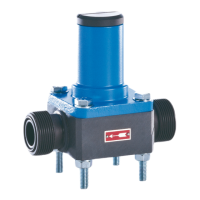
Diaphragm Relief Valve
Operating Instructions
Subject to technical modifications!
1 General
Before commissioning and during operation of the sera dia-
phragm relief valve the respective regulations valid at the place
of installation are to be observed.
sera diaphragm relief valves are delivered ready for assembly.
Carefully read these instructions and especially the safety in-
structions herein contained before installation and initial start-
up of the valves.
The sera diaphragm relief valve protects the pump, fittings,
and pipes from unacceptable overpressure.
2 Types
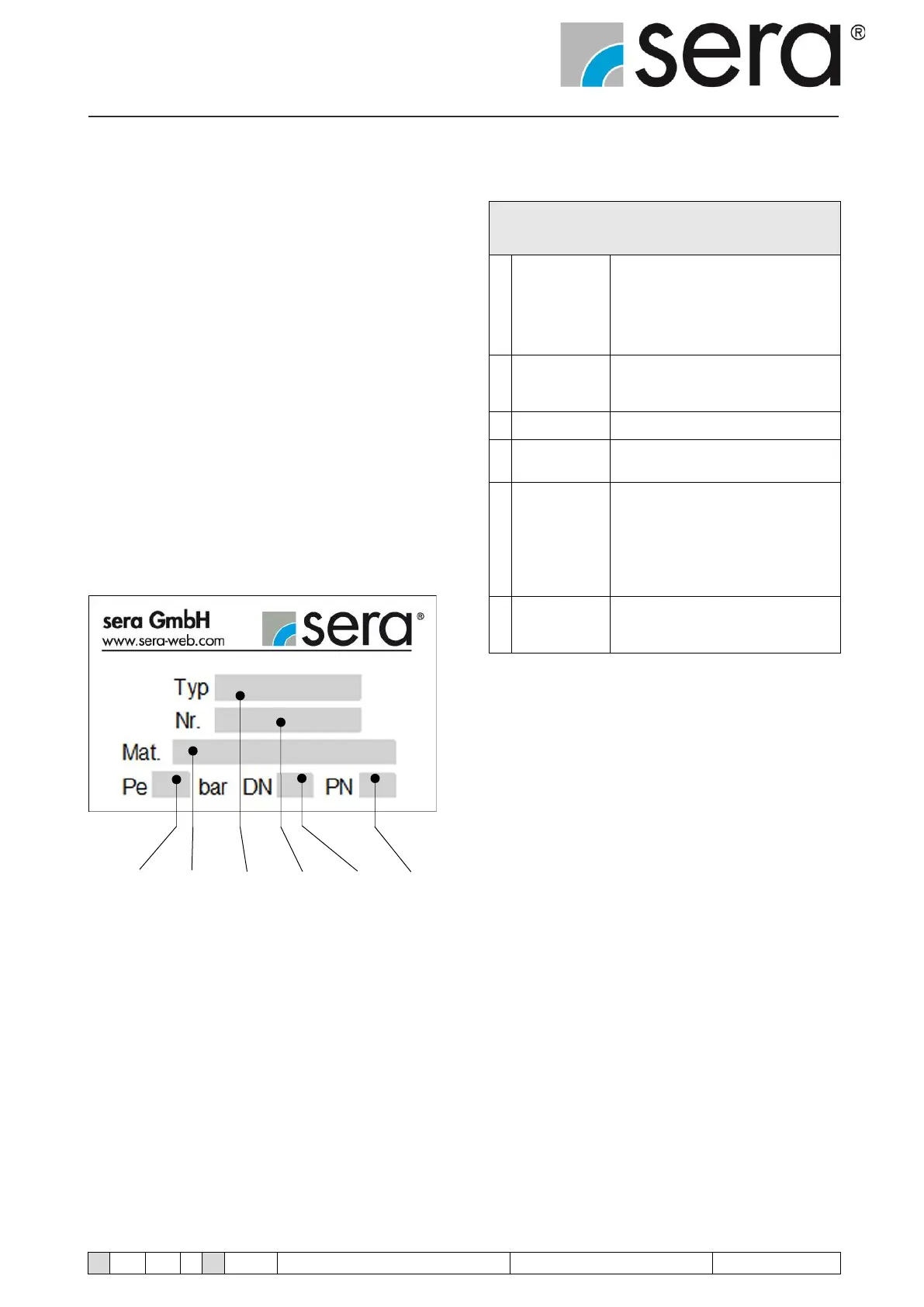
2.1 Type plate
Each sera diaphragm relief valve is factory provided with a
type plate. The following information can be found on this type
plate.
1 2 3 4 5 6
Fig. 01 Type plate
Explanation of the indications on the type
plate
Set pressure:
The set pressure corresponds to the
overpressure (at the valve inlet) at
which the valve opens under test condi-
tions (atmospheric pressure at the valve
outlet).
Materials:
Material specifications for housing / dia-
phragm according to DIN/ISO
Diaphragm relief valve type
Serial number of the diaphragm relief
valve
Nominal width:
The nominal width is a characteristic
parameter which is used for pipes and
parts, e.g. tubes, tube connections, fit-
tings etc. matching each other.
Nominal widths correspond to the pipe
diameter in mm.
Nominal pressure:
The nominal pressure is the permissible
operating pressure in bar at 20° C.
Table 01 Explanation of type plate