SCORPIO LIGHT SERIES 10’/17’/23’L - PARTS AND COMPONENTS DESCRIPTION - Electronic box (E.B.)
Version 1.04 May 26, 2022
28
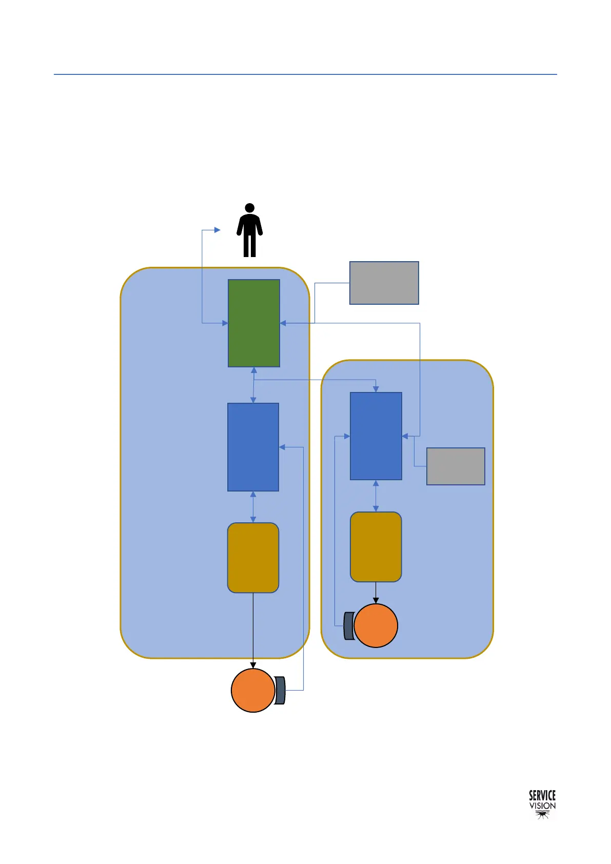
2.5.3 KEY CONCEPTS
All the Scorpio Systems works in a similar way: The user interface with the system using different
kind of peripherals (the hand command to tell the system to move or the display to read information
and use functions for example). The CCU board is the one that manages this interaction. Depending
on the specific function that the system has to do (which motor has to move for example), it sends the
order to the proper Servo board. This Servo board uses a driver or amplifier to move the motor
assigned to it. There are control systems attached to the motors (encoder for example) to control the
position of the motor and give this information back to the Servo.
CCU
2000
 Loading...