SCORPIO LIGHT SERIES 10’/17’/23’L - SPECIAL CONFIGURATIONS - M.G. with Scorpio Focus
Version 1.04 May 26, 2022
82
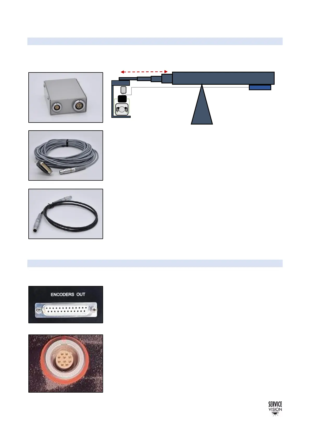
8.4 M.G. WITH SCORPIO FOCUS
Using the encoder output of the crane, it is possible to send the encoder signal of the telescopic arm
into the M.G. connector of the Scorpio Focus to record focal and zoom points depending on the
extension of the arm.
To connect the encoder from the arm into the M.G. of the Scorpio
Motor driver box it is necessary to adapt the encoder signal using the
encoder signal converter (fig. 08.34). The encoder cable from the E.B.
(fig.08.35) sends the signal into the converter and from the converter
into the M.G. connector of the motor driver box using the 4 pin Lemo
cable (fig. 08.36).
Once everything is connected, link the motor driver box with the
Scorpio focus hand command by cable or by radio and activate the
motion generation feature.
When the extension of the arm changes, the motor driver box will
detect that change and will allow the user to record points depending
on the extension of the arm.
8.5 AUGMENTED REALITY
Servicevision products are equipped with encoder output connectors. From those connectors it is
possible to read the number of pulses and with the encoder resolution and the gear factors provided
in the documentation chapter of the manuals it is possible to have an
accurate reading of the movement of the cranes and heads.
This information can be used in real time to generate graphics in the
virtual set using different software providers.
 Loading...