Home
Servomex
Measuring Instruments
SERVOTOUGH Oxy
Servomex SERVOTOUGH Oxy User Manual
4
of 1
of 1 rating
145 pages
Give review
Manual
Specs
To Next Page
To Next Page
To Previous Page
To Previous Page
Loading...
4
©
Ser
vo
m
ex
Group L
imited. 2
020
01910001B_8
2 -
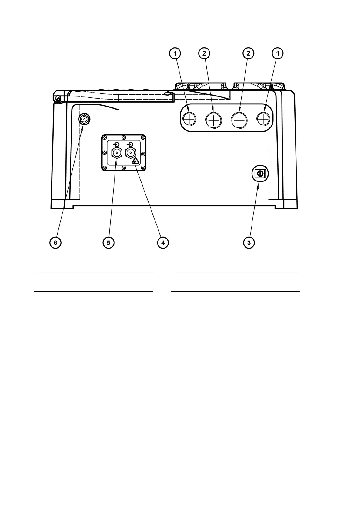
Key
Key
1.
2.
5.
3.
6.
15
17
Table of Contents
Table of Contents
5
Description and Definitions
13
Descrip�On
13
Construc�On
13
Sample/Control Compartment
13
Power/Signal Compartment (Figure 4)
14
Ordering Op�Ons
14
Figure 1 - Front of the Analyser
15
Figure 2 - Base of the Analyser
16
Figure 3 - Base of Analyser, Sample Hea�Ng
17
Figure 4 - Inside Power / Signal Compartment
18
Figure 5 - Inside Power / Signal Compartment - Auto Valida�On / Remote Calibra�On
19
Specification
21
General
21
Environmental Limits
21
Electrical Data
22
Sample Gas
23
Corrosive Purge Gas
24
Calibra�On Gas
24
Performance
25
Hazardous Area Cer�Fica�On
27
Unpack the Analyser
29
Analyser User Interface
31
Introduc�On
31
Start-Up and Measurement Screens
31
So� Key Legends
32
Figure 6 - the Measurement Screen
32
System and Measurement Status Icons
33
Scroll Bars
34
Menu Op�Ons/Screens and Password Protec�On
34
Figure 7 - the Analyser Menu Structure
35
The Menu Screen
36
The Se�Ngs Screen
36
Figure 8 - the Menu Screen
36
The Informa�On Screen
37
Figure 9 - the Se�Ngs Screen
37
Figure 10 - Typical Informa�On Screen
37
Edi�Ng On-Screen Data
38
Figure 11 - a Typical Edit Screen
38
Installation and Set-Up
39
Mechanical Installa�On
39
Figure 12 - Fixing Dimensions (MM)
41
Remove the Power/Interface Compartment Cover
42
Figure 13 - Fixing Dimensions Cont. (MM)
42
Electrical Supply and Interface Signal Connec�Ons
43
Electrical Safety
43
Configure the Cable Entry Holes
44
Interface Signal Connec�Ons
44
Auto Validate/Calibrate Connec�Ons (Op�On)
46
Modbus RS485 and Ethernet Connec�Ons (Op�On)
47
Figure 14 - Modbus RS485 Interface Connector
47
Mains Electrical Supply Connec�On
48
Refit the Power/Interface Compartment Cover
48
External Earth (Ground) Connec�On
49
Connect the Sample/Calibra�On Gas Pipe(S)
50
Switch On/Set-Up
51
Selec�Ng the Security Level and Password(S)
51
Se�Ng the Security Level
52
Changing Passwords
52
Figure 15 - the Security Level Screen
52
Figure 16 - the Security Select Screen
52
Adjus�Ng the Contrast
53
Adjus�Ng the Backlight �Mer
53
Figure 17 - the Edit Supervisor Password Screen
53
Figure 18 - the Contrast Screen
53
Figure 19 - the Backlight �Mer Screen
53
Se�Ng the Clock
54
Changing Regional Se�Ngs
54
Figure 20 - the Clock (�Me) Screen
54
Figure 21 - the Clock (Date) Screen
54
Se�Ng up Automa�C Valida�On/Calibra�On (Op�On)
55
Overview of Automa�C Valida�On/Calibra�On
55
Figure 22 - the Regional Se�Ngs (Language) Op�On Screen
55
Automa�C Valida�On/Calibra�On Sequence
57
Remote Calibra�On or Automa�C Valida�On/Calibra�On
58
Figure 23 - Typical Automa�C Calibra�On Sequence
58
Automa�C Valida�On/Calibra�On Target and Tolerance
59
Figure 24 - the Auto Val/Cal Parameters Screen
59
Figure 25 - the Auto Val/Cal Low Target Value Screen
59
Figure 26 - the Auto Val/Cal Low Tolerance Screen
59
Automa�C Valida�On/Calibra�On Type and Mode
60
Automa�C Valida�On/Calibra�On Phases
60
Figure 27 - the Auto Val/Cal High Target Value Screen
60
Figure 28 - the Auto Val/Cal High Tolerance Screen
60
Figure 29 - the Auto Val/Cal Type Screen
60
Figure 30 - the Auto Val/Cal Mode Screen
60
Figure 31 -The Auto Val/Cal Phase Screen
61
Figure 32 - the Auto Val/Cal Pre- Warning �Mer Screen
61
Figure 33 - the Auto Val/Cal Iner�Ng Screen
61
Figure 34 - the Auto Val/Cal Inert Gas Screen
61
Automa�C Valida�On/Calibra�On �Mers
62
Figure 35 - the Auto Val/Cal Iner�Ng �Mer Screen
62
Figure 36 - the Auto Val/Cal Flushing Screen
62
Figure 37 - the Auto Val/Cal �Mer Screen
62
Figure 38 - the Auto Val/Cal Start Date Screen
62
Configuring and Using the Ma Outputs
63
Overview
63
Figure 39 - the Auto Val/Cal Start �Me Screen
63
Figure 40 - the Auto Val/Cal Repeat �Me Screen
63
Introduc�On to the Ma Output Parameters
64
Se�Ng up the Ma Output Parameters
66
Figure 41 - the Ma Configura�On Screen
66
Figure 42 - the Ma Range Screen
66
Figure 43 - the Ma Output High Level Screen
67
Figure 44 - the During Calibra�On Screen
67
Figure 45 - the Jam Condi�On Screen
67
Figure 46 - the Ma Output Range Screen
67
Calibra�Ng the Ma Output
68
Figure 47 - the Ma under Range Screen
68
Figure 48 - the Ma Range Change Point Screen
68
Figure 49 - the Ma Range Change Hysteresis Screen
68
Configuring and Using the Relay Outputs
69
Overview Relay Default Status Se�Ngs
69
Figure 50 - the Ma Output Service Screen
69
Figure 51 - the Ma Output Calibrate Screen
69
Se�Ng up the Relay Coil Status
70
Figure 52 - Fault Relay
70
Figure 53 - Maintenance Required
71
Figure 54 - Service in Progress
71
Figure 55 - Alarm 1
71
Figure 56 - Alarm 2
71
Correc�Ng O 2 Measurements for Background Gases
72
Overview of Measurement Errors
72
Figure 57 - Ma Range Indica�On
72
Entering a Cross-Interference Compensa�On
73
Selec�Ng Display Units
73
Figure 58 - the X-Interference Offset Screen
73
Figure 59 - the Currently Selected Units Screen
74
Configuring the Measurement Alarms
75
Alarm Modes and Levels
75
Figure 60 - the Units Selec�On Screen
75
Figure 61 - the Units Conversion Factor Screen
75
Figure 62 - the Alarm Set up Screen
76
Figure 63 - the Alarm Mode Screen
76
Latching/Non-Latching Alarms
77
Hysteresis Levels
77
Figure 64 - the Alarm Follow Screen
77
Figure 65 - the Alarm Follow Op�Ons Screen
77
Viewing the Measurement Alarm Status
78
Se�Ng the Measurement Filter Level
78
Figure 66 - the Alarm Status Screen
78
Se�Ng up the Flowcube
79
Flow Sensor (Op�On)
79
Figure 67 - Filter Factor Screen
79
Figure 68 - Filter Factor Edit Screen
79
Figure 69 - the Low Flow Level 1 Screen
80
Figure 70 - the Low Flow Level 2 Screen
80
Figure 71 - the Low Flow 1 Status Screen
81
Figure 72 - the Low Flow 2 Status Screen
81
Figure 73 - the High Flow Status Screen
81
Calibration
83
Manual Calibra�On
83
Automa�C Valida�On/Calibra�On
84
Ini�A�Ng an Automa�C Valida�On/Calibra�On
84
Figure 74 - the Calibrate Screen
84
Figure 75 - the Calibrate Target Value Screen
84
Figure 76 - the Auto Val/Cal Select Screen
85
Figure 77 - the Auto Val/Cal Ini�Ate Screen
85
Figure 78 - the Auto Val/Cal Confirm Screen
85
Automa�C Valida�On/Calibra�On Status Indica�Ons
86
Stopping an Automa�C Valida�On/Calibra�On
86
Figure 79 - the Auto Val/Cal Status Screen (Flushing Phase)
86
Figure 80 - the Auto Val/Cal Status Screen (Valida�Ng Phase)
86
Figure 81 - the Auto Val/Cal Status Screen (Finishing Phase)
86
Figure 82 - the Auto Val/Cal Failed Screen
86
Viewing Valida�On/Calibra�On History
87
Figure 83 - the Auto Val/Cal Stop Confirma�On Screen
87
Figure 84 - the Valida�On/Calibra�On History Screen (Ini�Al View)
87
Calibra�Ng the Pressure Sensor
88
Calibra�Ng the Flowcube (F 3 ) Flow Sensor (Op�On)
88
Figure 85 - the Valida�On/Calibra�On History Screen (Alternate View)
88
Figure 86 - the Flow Calibrate Zero Screen
88
Figure 87 - the Flow Calibrate Normal Screen
88
General Operation
89
Checking the Relay Signal Outputs
89
Figure 88 - the Relay Override State Screen
89
Figure 89 - the Relay Override Ac�On Screen
89
Pressure Compensa�On (Op�On)
90
Introduc�On
90
Switching Pressure Compensa�On On/Off
90
Viewing Pressure Effected Measurements
90
Figure 90 - the Pressure Compensa�On
90
Checking the Ma Output
91
Viewing Flow Levels
91
Figure 91 - the Pressure View Screen
91
Figure 92 - the Ma Output Override
91
Switching off the Analyser
92
Figure 93 - Flow Levels
92
Routine Maintenance
93
Cleaning the Analyser
93
Inspec�On
93
Inspec�Ng/Replacing the Fuse (When Necessary)
93
Refit the Power/Interface Compartment Cover
94
Use of the Analyser with Toxic Gases
95
Preventa�Ve Maintenance
95
Sample System Integration
97
Sample Systems
97
Corrosive Purge
97
Fault Finding
99
Fault, Maintenance Required and SIP Statuses
99
Status Defini�Ons
99
Status Annuncia�Ons
99
Viewing Messages
104
Ac�Ve Messages
104
View History Messages
105
General Fault Finding
105
Figure 94 - the Message Status Screen
105
Figure 95 - the Message Status Screen
105
Storage and Disposal
109
Storage
109
Disposal
109
Spares
111
Implementation Guide for Modbus Communications
113
Introduc�On
113
References
113
Modbus Setup
113
Supported Func�On Codes
113
Excep�On Codes
114
Addressing
114
Floa�Ng Point Numbers
114
System Data Mapping
114
Transducer Data Mapping
115
A.10 System Fault Mapping
116
A.11 Transducer Fault and Alarm Mapping
117
A.12 System Setup Mapping
120
A.13 Transducer Setup Mapping
120
A.14 System Control
123
A.15 Transducer Control
124
Configuring the Modbus Parameters
127
Figure 96 - Comms Parameters Mode Screen
127
Figure 97 - Comms Parameters Node Address Screen
127
TCP (Ethernet)
128
Figure 98 - Comms Parameters Baud Rate Screen
128
Figure 99 - Comms Parameters Parity Screen
128
Figure 100 - Comms Parameters IP Address Screen
128
Figure 101 - Comms Parameters Subnet Mask Screen
129
Figure 102 - Comms Parameters Gateway Address Screen
129
Display Unit Conversion Factors
131
Appendix Dparamagnetic CORRECTION FACTORS
133
Appendix Ematerials in CONTACT with SAMPLE and CALIBRATION GASES
141
Appendix Fdisposal in ACCORDANCE with the WASTE ELECTRICAL and ELECTRONIC EQUIPMENT (WEEE) DIRECTIVE
143
Appendix Gcompliance and STANDARDS INFORMATION
145
4
Based on 1 rating
Ask a question
Give review
Questions and Answers:
Need help?
Do you have a question about the Servomex SERVOTOUGH Oxy and is the answer not in the manual?
Ask a question
Servomex SERVOTOUGH Oxy Specifications
General
Brand
Servomex
Model
SERVOTOUGH Oxy
Category
Measuring Instruments
Language
English
Related product manuals
Servomex SERVOPRO FID
67 pages
Servomex SERVOPRO 4100
74 pages
Servomex SERVOFLEX MiniMP
104 pages
Servomex SERVO PRO 14440D1
38 pages
Servomex SERVOPRO MultiExact
145 pages
Servomex SERVOPRO 4000 Series
74 pages
Servomex 2700
40 pages

 Loading...


