R..7, F..7, K..7, S..7, Spiroplan
®
W Gear Units – Operating Instructions
15
4
Mechanical Installation
4.5 Gear units with solid shaft
Installation of
input and output
elements
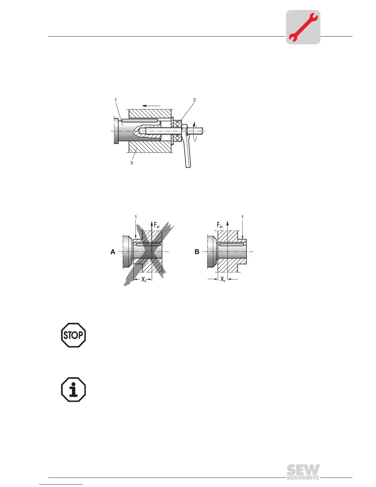
The following illustration is an example of a moutning device for mounting couplings or
hubs onto gear unit or motor shaft ends. It may be possible to dispense with the thrust
bearing on the mounting device.
The following illustration displays the correct mounting arrangment B of a gear wheel or
sprocket to prevent excessively high overhung loads.
• Only use a mounting device (see Fig. 1) for installing input and output elements.
Use the center bore and the thread on the shaft end for positioning purposes.
• Power transmission elements should be balanced after fitting and must not give rise
to any impermissible radial or axial forces (see Fig. 2 / permitted values see the
"Geared Motors" catalog).
03371BXX
1) Gear unit shaft end
2) Thrust bearing
3) Coupling hub
03369BXX
1 = Hub
A = incorrect
B = correct
• Never drive belt pulleys, couplings, pinions, etc. onto the shaft end by hitting
them with a hammer (damage to bearings, housing and the shaft!).
• In the case of belt pulleys, make sure the belt is tensioned correctly (in accor-
dance with the manufacturer's instructions).
Note:
Assembly is easier if you first apply lubricant to the output element or heat it up briefly
(to 80-100 °C).

 Loading...