Do you have a question about the SEW MOVIAXIS MX and is the answer not in the manual?
Defines authorized personnel for installation, startup, and service of the units.
Specifies the intended industrial and commercial applications for the servo drives.
Details electrical installation regulations, EMC compliance, and grounding requirements.
Confirms unit meets requirements for safe disconnection of power and electronic connections.
Covers safe operation practices, including monitoring devices and handling after disconnection.
Describes the multi-encoder card option for evaluating additional encoders.
Describes the PROFIBUS fieldbus interface option for communication.
Describes the K-Net fieldbus interface option for serial bus systems.
Details the EtherCAT fieldbus interface option for EtherCAT networks.
Explains the EtherCAT-based system bus option for axis-internal expansion.
Covers essential aspects of mechanical installation, including mounting and clearances.
Specifies minimum clearance requirements for cooling and correct mounting positions.
Provides critical guidelines for safe electrical installation, including voltage hazards and grounding.
Covers connecting supply terminals, grounding, and preventing inadvertent motor start-up.
Introduces wiring diagrams and general notes on connections.
Shows wiring diagrams for power terminals of various modules.
Illustrates wiring diagrams for multiple modules including brake and power supply.
Presents wiring diagrams for different brake control variants.
Shows wiring diagrams for the control electronics of supply modules.
Details wiring diagrams for the control electronics of axis modules.
Shows wiring diagrams for the master module component.
Details wiring diagrams for the capacitor module component.
Illustrates wiring diagrams for the buffer module component.
Shows wiring diagrams for the 24 V switched-mode power supply module.
Explains how to connect encoders to the MOVIAXIS® basic unit.
Offers guidance on EMC compliance, including cable routing and shielding.
Recommends EMC measures for limiting interference emission on supply and motor ends.
States compliance with category "C2" according to EN 61800-3 for interference emission.
Provides key points for UL-compliant installation, including cable types and tightening torques.
States that correct drive configuration is necessary for successful startup.
Warns that MOVIAXIS® is not designed as a safety device in hoist applications.
Details necessary settings for the supply module in a CAN-based system bus.
Covers connecting the PC to the system for diagnostics and specifies cable length limits.
Provides information and settings for the CAN2 bus system.
Describes using a CAN adapter for PC communication with the MOVIAXIS® system.
Details the settings required for an EtherCAT-based system bus configuration.
Introduces the MOVITOOLS® MotionStudio software for system startup.
Details the procedure for starting up the system in single-motor operation mode.
Explains options for data transfer from SEW encoders during startup.
Details how to manage encoder data for non-SEW encoders.
Allows selection of drive configurations: single drive or multiple drives.
Outlines the steps for a complete startup sequence.
Guides the selection of the motor type connected to MOVIAXIS®.
Covers settings for monitoring speed, deceleration time, and current limit.
Explains how to enter values for the speed controller parameters.
Describes how to configure axis parameters like travel distance, velocity, and acceleration.
Defines application and system limits for velocity, acceleration, and deceleration.
Describes the process of downloading calculated startup parameters to the axis module.
Details parameters related to the Pxxx speed control loop.
Outlines the startup procedure for multi-motor operation.
Explains encoder management for multi-motor configurations.
Guides the selection of encoders for multi-motor setup.
Details encoder signal processing and emulation options.
Shows using a linear encoder for position control in specific applications.
Demonstrates multi-motor operation, connecting up to three motors to one axis module.
Explains how to use the PDO Editor to set process data for communication.
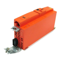
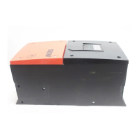
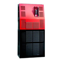
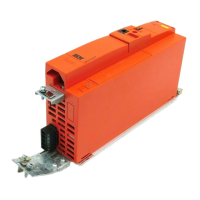
Provides general safety and operational information for the MOVIAXIS® MX multi-axis servo drive.
Warns about dangerous voltages at terminals and cables during operation.
Highlights the risk of crushing due to unintentional motor startup and safety precautions.
Explains the operating displays and error indications on supply and axis modules.
Provides a list of errors, their causes, responses, and reset types.
Explains different error reset types: CPU reset, System restart, and Warm start.
Details operating displays and error codes specific to the MXP supply module.
Describes operating displays and error codes for MXA axis modules.
Presents a comprehensive table of error codes, messages, and causes for MXA axis modules.
Details errors related to speed monitoring, including deviations and limit violations.
Covers errors related to axis module over-temperature and its possible reasons.
Lists errors related to the brake output, such as disconnection or overload.
Details errors concerning the brake supply voltage range.
Covers errors related to resolver connection or evaluation.
Addresses errors in Hiperface signal checksum comparison.
Lists errors that can occur during the startup process, including parameter issues.
Details errors related to accessing non-volatile parameter memory.
Covers errors reported by binary input terminals.
Lists errors related to limit switch detection or reversal.
Addresses errors due to interrupted process data communication.
Covers errors occurring during travel to hardware limit switches.
Details errors related to the drive not stopping within the preset delay time.
Lists errors related to motor thermal protection and sensor issues.
Covers errors where the following error exceeds permitted limits during positioning.
Details errors during remote control via serial interface.
Lists errors related to inverter overload and chip temperature.
Covers errors occurring during system initialization processes.
Addresses errors related to communication interruptions on SBUS#2.
Lists errors related to incorrect or defective 24V supply voltage.
Covers errors when a software limit switch is approached during positioning.
| Series | MOVIAXIS MX |
|---|---|
| Type | Inverter |
| Protection class | IP20 |
| Altitude | Up to 1000 m without derating |
| Output voltage range | 0...max. input voltage |
| Output frequency range | 0...400 Hz |
| Power range | Up to 315 kW |
| Cooling method | Forced air cooling |
| Communication interfaces | Ethernet, PROFIBUS, CANopen |
| Storage temperature range | -25°C to +70°C |
| Relative humidity | 5-95% (non-condensing) |