SANITOP PAGE 9
1 2
3 4
5 6
7 8
9 10
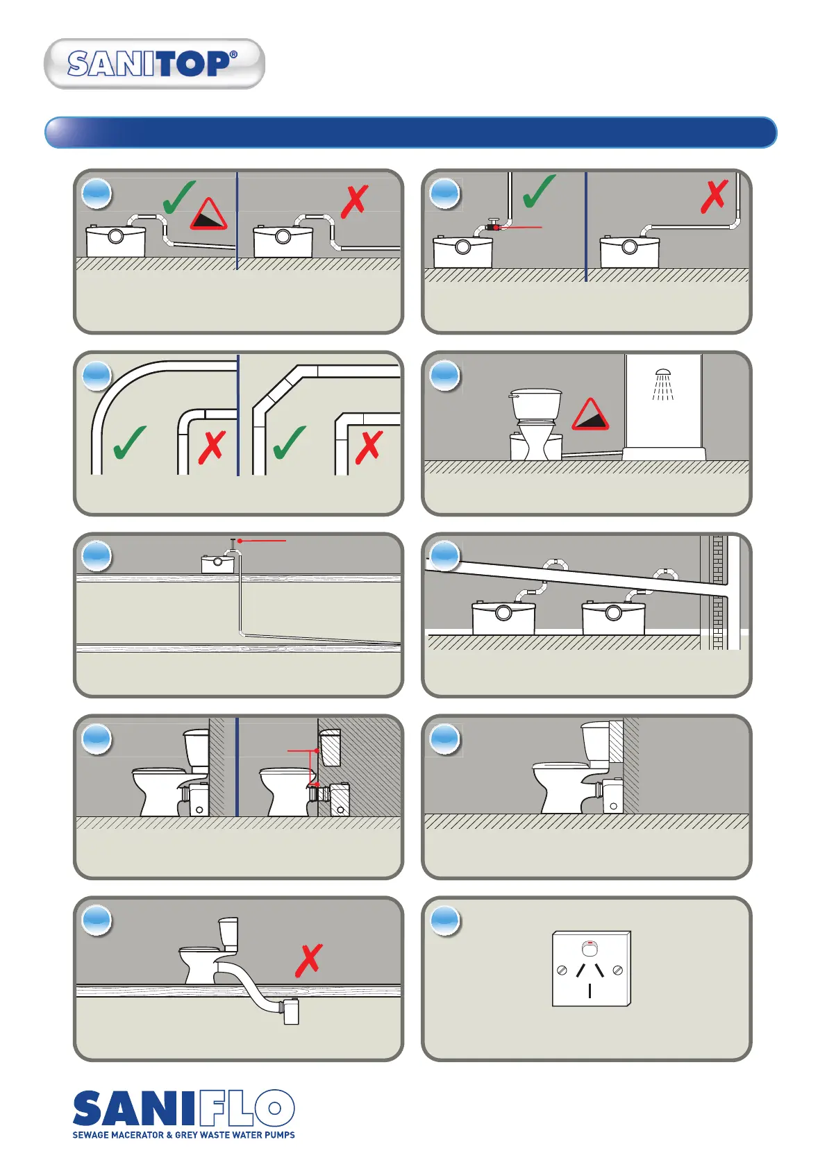
All horizontal pipes should have a minimum fall of 1:100.
Discharge pipework should be solvent UPVC.
Do not “pushfit” pipework/fittings.
If a vertical rise is needed, this should be at the start of the run
(within 30cm of the unit).
Bends should be smooth/long radius, not tight elbows.
Examples of uPVC Pressure Pipe and fittings shown.
Waste Pipes entering the Saniflo unit should have a
gravity fall of 1:40
2 x 45˚ Offset
Plastic Elbows
Where the pipework falls below floor level, fit an air admittance
valve at the highest point capable of withstanding 10psi neg
pressure, or upsize pipe coming down to break syphonage.
Each Saniflo discharge pipe should run separately to the sewer/vent
pipe. If wastes are combined, it can only be connected to a larger pipe.
This pipe must gravity fall to connection point.
The unit should be easily accessible and removable in the event of service
or maintenance being required. If boxed in, the boxing should be easily
removed. Any extension between the WC pan spigot and wall should not
exceed 150mm and have a 1.40 fall.
As close coupled cistern dimensions vary it may be
necessary with certain designs to utilise a spacer between
cistern and wall.
Position the Saniflo unit directly behind the toilet pan,
not underneath it.
Connect to power according AS/NZS 3000: 2007 Electrical Regulation
as rules apply depending on location. In ALL CASES
supply must be protected by a 30mA RCD rated at 16A.
Easily
removable
panels
Air admittance
valve
1:100
PVC
Ball Value
ELECTRICAL CLASS 1 PRODUCT
After sales contact information: info@saniflo.com.au
15. Ten golden rules for correct installation