9
3. ELECTRICAL CIRCUIT CONTROL
3-1 Electrical Wiring
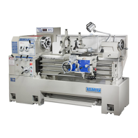
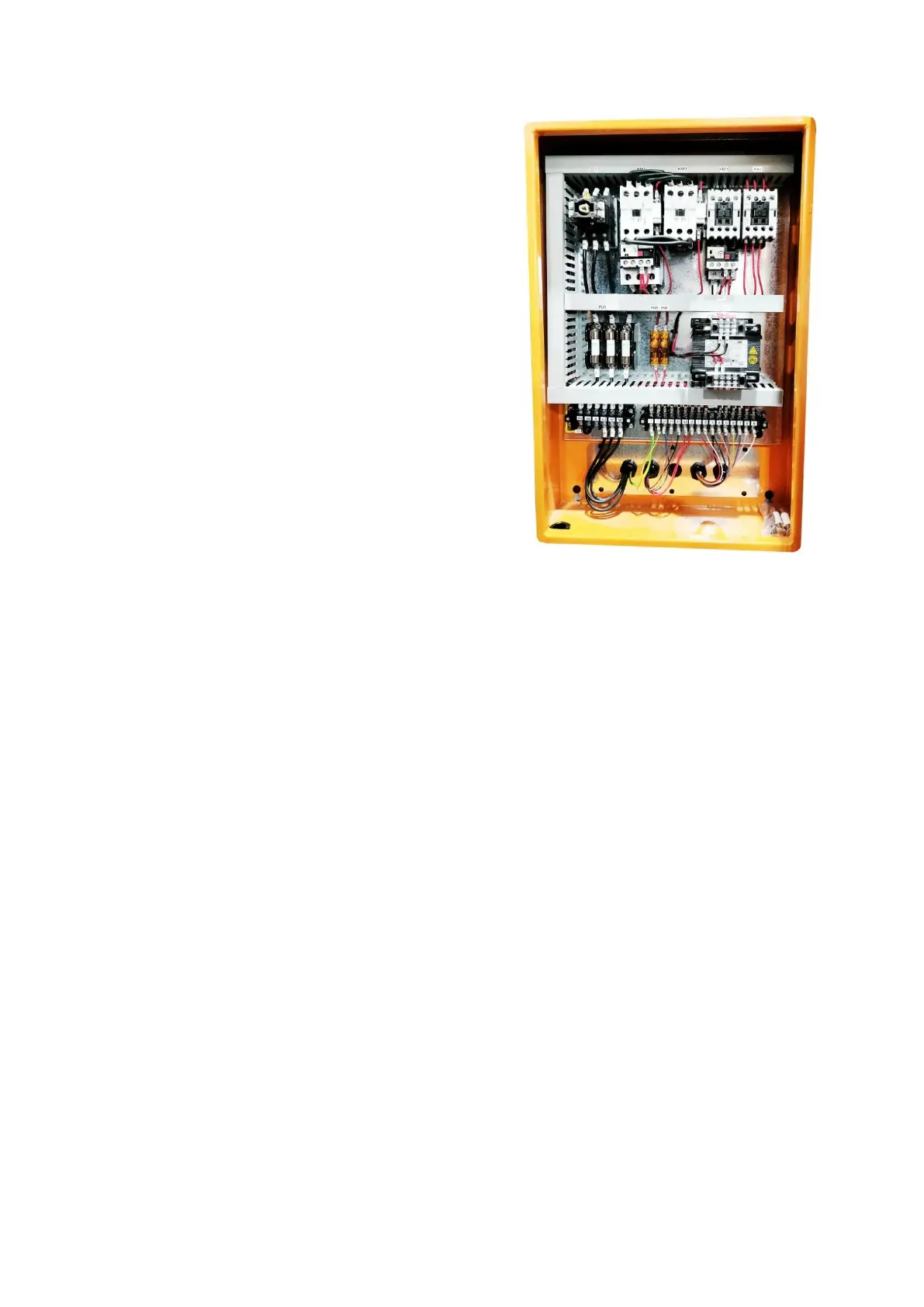
The electrical control box can be found by
opening its cover at the back side of bed.
Connect the power source wire with the
connecting points (R.S.T).
The wire between the power source and the
connecting points must be over sectional area
8mm
2
(5.5 mm
2
for 460 or 18” series).
The main switch between machine and
power source should be equipped with safety
fuse. Besides, the machine must have a earth
wire.
3-2 Electrical Equipment
1. The electrical control box is also equipped with overload circuit breaker and
electric magnetic contactor to protect motor from burning out by overload.
2. The main switch is connected with a micro switch.
3. The foot brake is connected with micro switch. Stepping the footbrake is quicker
to stop the lathe than turning off the switch. The spindle can only revolute again
by re-operating the spindle operation control lever using the foot brake.
4. The spindle will rotate continuously as long as the intermittent switch on the top
of the electrical panel is pressed.
3-3 Electrical Cautions
After wiring, check the rotation of the spindle. Turn the main switch “ON” and
make sure the safety of spindle. Then push intermittent button ○
T
momentarily. The
correction direction of the spindle rotation is counter clockwise. (looking from
tailstock for a downward movement of the spindle operation control lever.) Wrong
direction of rotation can be rectified by interchanging any two of the three phase lines
(R.S.T.) in the power source.