AR-M350 SIMULATIONS 10-35
<List of display values>
*1: Only when this value is 0, control is performed with the actual
measurement value of process Thermistor.
If it is not 0, control is forcibly performed.
*2: When the drum motor standby time is greater than this value, the
correction of SIM 44-1 Vb1 is performed.
*3: This value is SIM 44-9 Vb1-1 correction value. The value
corresponding to the drum rotating time is used.
*4: This value is SIM 44-9 Vb1-2 correction value. The value
corresponding to the drum rotating time is used.
<List of display values>
*1: Vb1-1 and Vb1-2 are enabled or disabled by SIM 44-1 Vb1 setup.
*2: When PTH is set to 0 with SIM 44-4, the detected value in this
adjustment is displayed. If PTH is set to other than 0, the value set
with SIM 44-4 is displayed.
Main code 44
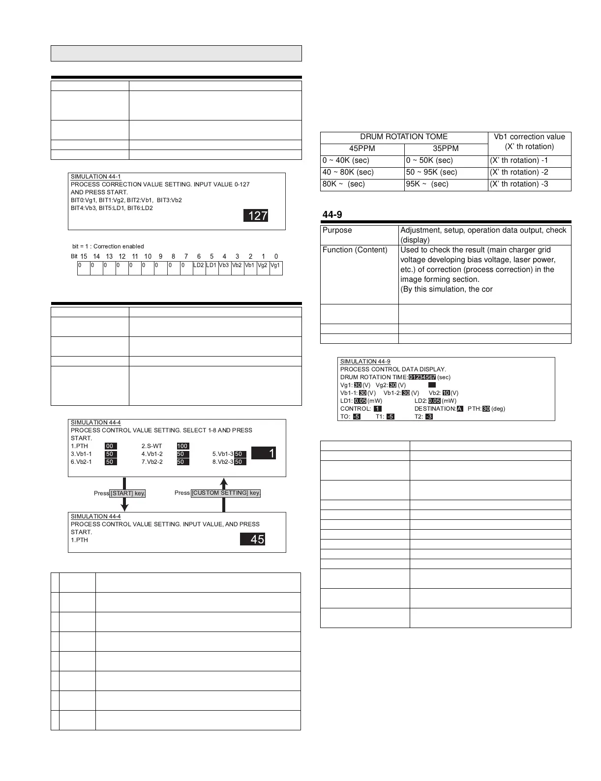
44-1
Purpose Setup
Function (Content) Used to set Enable/Disable of each correction
operation in the image forming (process)
section.
Section Process
(OPC drum, developing, transfer, cleaning)
Item Operation
Operation/Procedure
44-4
Purpose Setup
Function (Content) Used to set the target image (reference) density
level in the developing bias voltage correction.
Section Process
(OPC drum, developing, transfer, cleaning)
Item Data
Operation/Procedure The process correction value is set.
Select an item (1 - 9), and enter a value with
10 digit key pad. Press SYTART to store the
value.
1 PTH *1 Process Thermistor temperature forcible set value
(0-99°C : Normal 0)
2 S_WT *2 Vb (Devepoping bias correction value) rising correction
wait time (0-180sec : Default 90)
3 Vb1-1 *3 Vb (Devepoping bias correction value) correction quantity
(First rotation) 1 (0 - 150V : Default 50)
4 Vb1-2 *3 Vb (Devepoping bias correction value) correction quantity
(First rotation) 2 (0 - 150V : Default 50)
5 Vb1-3 *3 Vb (Devepoping bias correction value) correction quantity
(First rotation) 3 (0 - 150V : Default 50)
6 Vb2-1 *4 Vb (Devepoping bias correction value) correction quantity
(Second rotation) 1 (0 - 50V : Default 15)
7 Vb2-2 *4 Vb (Devepoping bias correction value) correction quantity
(Second rotation) 2 (0 - 50V : Default 15)
8 Vb2-3 *4 Vb (Devepoping bias correction value) correction quantity
(Second rotation) 3 (0 - 50V : Default 15)
SIMULATION 44-1
PROCESS CORRECTION VALUE SETTING. INPUT VALUE 0-127
AND PRESS START.
BIT0:Vg1, BIT1:Vg2, BIT2:Vb1, BIT3:Vb2
BIT4:Vb3, BIT5:LD1, BIT6:LD2
127
0
15
0
14
0
13
0
12
0
11
0
10
000
9 8 7
LD2
6
LD1
5
Vb3
4
Vb2
3
Vb1
2
Vg2
1
Vg1
0
Bit
bit=1:Correction enabled
1
SIMULATION 44-4
PROCESS CONTROL VALUE SETTING. INPUT VALUE, AND PRESS
START.
1.PTH
45
SIMULATION 44-4
PROCESS CONTROL VALUE SETTING. SELECT 1-8 AND PRESS
START.
1.PTH 00 2.S-WT 100
3.Vb1-1 50 4.Vb1-2 50 5.Vb1-3 50
6.Vb2-1 50 7.Vb2-2 50 8.Vb2-3 50
Press [CUSTOM SETTING] key.
Press [START] key.
DRUM ROTATION TOME Vb1 correction value
(X’ th rotation)
45PPM 35PPM
0 ~ 40K (sec) 0 ~ 50K (sec) (X’ th rotation) -1
40 ~ 80K (sec) 50 ~ 95K (sec) (X’ th rotation) -2
80K ~ (sec) 95K ~ (sec) (X’ th rotation) -3
44-9
Purpose Adjustment, setup, operation data output, check
(display)
Function (Content) Used to check the result (main charger grid
voltage developing bias voltage, laser power,
etc.) of correction (process correction) in the
image forming section.
(By this simulation, the correction operation can
be checked.)
Section Process
(OPC drum, developing, transfer, cleaning)
Item Data
Operation/Procedure The process correction value is checked.
DRUM ROTATION TIME Drum rotation time
Vg1~Vg2 Grid voltage correction value
Vb1-1 *1 Vb (Developing bias correction value)
correction value (first rotation)
Vb1-2 *1 Vb (Developing bias correction value)
correction value (second rotation)
Vb2 Developing bias correction value
Vb3 Developing bias correction value
LD1 Laser power correction value
LD2 Laser power correction value
CONTROL CRUM control spec (1 - 3)
DESTINATION CRUM destination (A - J)
PTH *2 Process Thermistor temperature value
T0 Toner control correction value
(Rotation time correction) (±100)
T1 Toner control correction value T1
(Temperature correction) (±100)
T2 Toner control correction value T2
(Temperature correction) (±100)
SIMULATION 44-9
PROCESS CONTROL DATA DISPLAY.
DRUM ROTATION TIME:01234567 (sec)
Vg1: 30 (V) Vg2: 30 (V)
Vb1-1: 30 (V) Vb1-2: 30 (V) Vb2: 10 (V)
LD1: 0.05 (mW) LD2: 0.05 (mW)
CONTROL:1 DESTINATION: A PTH: 30 (deg)
TO: -5 T1: -5 T2: -3
( !" #$%&