11
AY-M09AE
AE-M18AE
Pin Terminal Input
No. Name Output Function
33 P56 OUT Serial signal Output
34 P57 OUT Serial signal Input
35 P60 IN Dry ON select
36 P61 OUT LED(Busy)
37 P62 OUT LED(Timer)
38 P63 OUT LED(Operation)
39 P64 OUT –
40 P65 OUT –
41 P66 OUT –
42 P67 OUT –
43 RESET IN Microcomputer reset input
44 INTP0 IN R.P.M signal input
45 INTP1 IN AC clock input
46 INTP2 IN Remote control signal
47 P03 OUT –
48 VDD – Power supply(5V)
49 X2 – Internal oscillation of the
microcomputer
50 X1 – Internal oscillation of the
microcomputer
51 IC – GND
52 XT2 – –
53 P04 IN Test mode
54 AVSS – GND
55 ANI0 IN Room temp. thermistor signal
56 ANI1 IN Pipe temp. thermistor signal
57 ANI2 IN –
58 ANI3 IN Model B select
59 ANI4 IN Model A select
60 ANI5 IN FAN L select
61 ANI6 IN FAN M select
62 ANI7 IN FAN H select
63 AVSS – 5V
64 AVREF – 5V
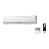
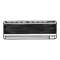
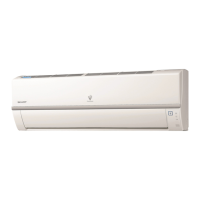
Microcomputer (IC1) for INDOOR UNIT
The microcomputer is a CMOS, one chip, 8-bit microcomputer.
Microcomputer port allocation is as follows.
Pin Terminal Input
No. Name Output Function
1 P20 IN 5V
2 P21 OUT –
3 P22 OUT E
2
PROM(IC6) clock Output
4 P23 IN/OUT Date transmition signal
5 P24 OUT –
6 P25 OUT –
7 P26 OUT –
8 P27 IN Preheat select
9 P30 IN Wireless select
10 P31 IN RPM select
11 P32 IN –
12 P33 IN –
13 P34 IN Sweat select
14 P35 IN –
15 BUZ OUT Buzzer signal
16 P37 OUT –
17 VSS – Power supply(0V)
18 P40 IN Power on start
19 P41 IN Auto restart
20 P42 IN –
21 P43 IN –
22 P44 IN Key in signal(AUX.)
23 P45 IN Key in signal(TEST RUN)
24 P46 IN GND
25 P47 IN GND
26 P50 OUT Louver motor control
27 P51 OUT Louver motor control
28 P52 OUT Louver motor control
29 P53 OUT Louver motor control
30 P54 OUT Indoor fan motor control
31 P55 OUT –
32 VSS – Power supply(0V)