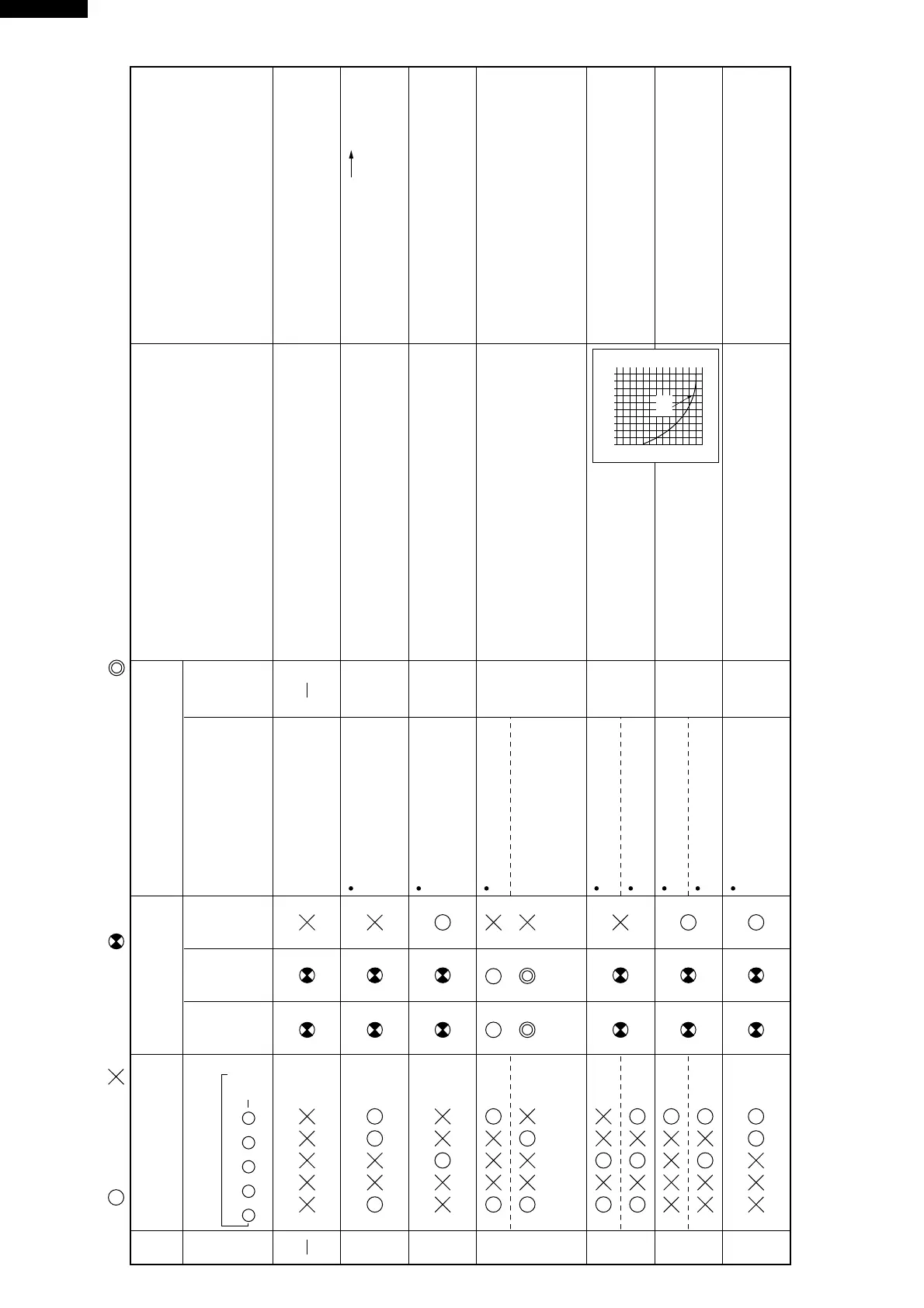
Self-diagnosis table (error information call-up)
: Turns ON.
Display with operation LED of
indoor unit
It is ON at the same time
when timer LED is ON.
Outdoor unit display LED
LED 1
Room
A1
Serial
SIGNAL
LED 2
Room
A2
Serial
SIGNAL
LED 3
Error
display
Diagnosis content
Content
Relevant
unit
Indoor
Outdoor
Indoor
Outdoor
Outdoor
No current flows in
the compressor.
Indoor or
outdoor
Check item Remedy
: Turns OFF. : Flickering at 2 seconds intervals. : Flickering at 0.2 seconds intervals.
Error
No.
1
2
3
4
5
6
x
1 2 3 4
4 sec.
OFF
5
x x x
Outdoor thermistor is
defective. Open circuit
Outdoor thermistor is
defective. Short circuit (0Ω)
Indoor thermistor is defective.
Short circuit (0Ω)
Indoor thermistor is defective.
Open circuit
Wiring connection
between the unit is improper.
Compressor is locked.
Indoor fan motor rotates
poorly.
No diagnosis information.
(1) Does indoor fan rotate ?
(2) Check the running capacitor.
(3)
Check the wiring and correction of the power supply to the compressor.
(2) Replace the running capacitor.
(3) Connect the wiring connection.
(4) Replace the compressor.
(2)
Unless LED flickers or lights, the outdoor control
circuit does not operate.
Refer to trouble shooting flow chart in Page 21 ~ 23.
(1)
Check the voltage of the power supply for 198 to 264V.
Check that the voltage drops when the compressor is started.
(1) Correct the wiring between the unit.
(2) Is LED 1 or LED 2 ON on the outdoor unit ?
(1) Check the connection of the
thermistor connector CN4.
(2) Check the resistance of the
thermistor.
(1) Check the connector of the
thermistor connector CN5.
(2) Check the resistance of the
thermistor.
(1) Is RY1(room A1) or RY2(room A2) on ?
(For check try to TEST RUN the indoor unit.)
(2)
Check the connection of compressor from RY1 and RY2.
(3) Check compressor motor protector for activation.
(2) Check the connected and soldered state of CN5.
(3) Is rotation pulse input to the terminals No. 2 and 3
of CN5. ?
(1) Fan or fan motor locked Replace
(1) Improve the power supply.
(1)
Since the parts of the control circuit may be
broken, replace the control circuit in the indoor
and outdoor units.
For the circuit repairing method, refer to Page 19.
(1) Improve connection state.
(2) Replace the thermistor.
(1) Improve connection state.
(2) Replace the thermistor.
(1) Replace the outdoor control board unit.
(2) Connect the wiring connection.
(3) Connect the cause of the overloaded
operation.
(2) Correct the connecting solder or replace the
control board unit.
CHARACTERISTIC OF TH1 & TH2
0
-10 0 10 20 30 40˚C
20
40
60
80
100
120
kΩ
25˚C
15kΩ