AYXP9LSR
3 – 11
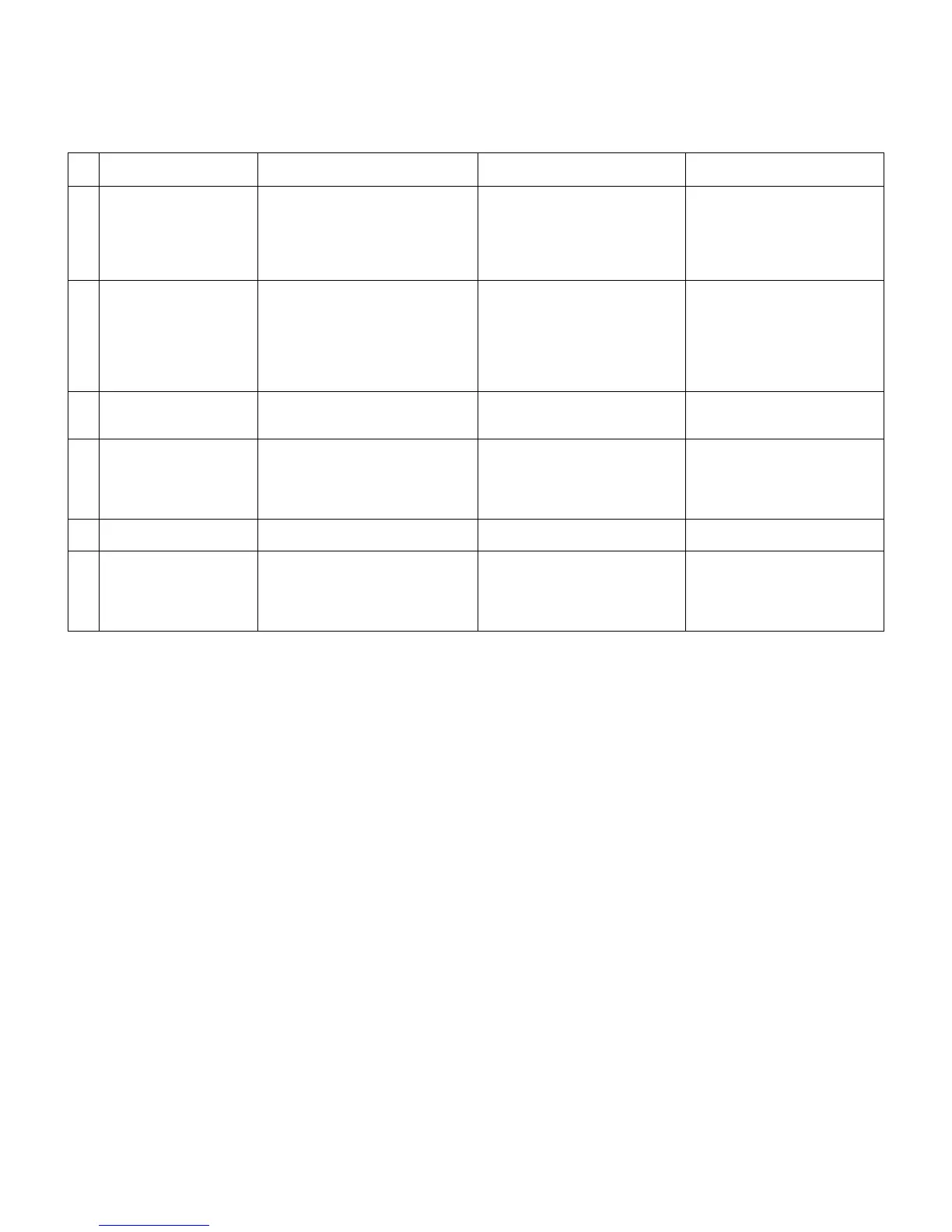
[7] OUTDOOR UNIT CHECK METHOD
After repairing the outdoor unit, conduct the following inspection procedures to make sure that it has been repaired completely. Then, operate the
compressor for a final operation check.
1. Checking procedures
No
.
Item Check method Normal value/condition Remedy
1 Preparation Disconnect compressor cords (white,
orange, red: 3 wires) from compres-
sor terminals, and connect simulated
load (lamp used as load).
Operate air conditioner in cooling or
heating test operation mode.
2 Inverter DC power supply
voltage check
Measure DC voltage between IPM
pins (20) and (24).
320 VDC Replace control PWB.
Replace diode bridge.
Correct soldered section of Fas-
ten tabs (BT1, BT2, BT5, 6, 10, 11
JPL1, 2, 5, 6) on control PWB and
IMP (S, C, R). (Repair solder
cracks.)
3 IPM circuit check Check that 3 lamps (load) light.
Check position detection voltage (+15
V, 5 V) on control PWB.
Each voltage should be normal.
All 3 lamps (load) should light with
same intensity.
Replace control PWB.
4 Compressor check Measure compressor coil resistance
(for each phase of U, V and W).
Use multi-meter or digital tester capa-
ble of displaying two digits right of the
decimal point (0.01Ω).
Resistance value at 20°C --- 0.65Ω Correct connections at compres-
sor terminals.
Replace compressor.
5 Expansion valve check Measure expansion valve coil resis-
tance.
Each phase 46±3Ω (at 20°C) Replace expansion valve.
6 Final check Turn off power, and connect compres-
sor cords to compressor.
Operate air conditioner.
Measure DC voltage between IPM
pins (20) and (24).
Compressor should operate nor-
mally.
200 VDC or higher.
Replace control PWB.
Replace outdoor unit thermistor.
Replace compressor (in case of
compressor lock).